Hybrid electric UAS propulsion combines a fuel-powered energy source with electrical propulsion and battery storage. It lets an unmanned aircraft carry fuel for sustained operation while using a battery to supplement power or support an engine-off segment. The benefit depends on the architecture, installed mass, and mission: a fuel supply can remain plentiful while the battery reserve needed for the next maneuver is already exhausted.
This explanation focuses on combustion-engine and battery systems. Readers comparing energy-source architectures can use the separate guide to hydrogen fuel cells for long-endurance drones for that alternative; the configurations below retain the combustion-engine focus. The useful starting point is to trace what turns the propeller, then identify which source can supply that power throughout the flight. A combination of vertical lift and wingborne flight describes an airframe capability; it does not, by itself, identify the propulsion energy sources.
On This Page
- Series, parallel, and combined architectures
- How the electrical power path works
- How power is shared during a mission
- A worked power and reserve example
- Interfaces and failures that matter
- Performance tradeoffs and representative applications
- What to establish before selecting an architecture
Series, parallel, and combined architectures
The architecture describes the route between energy sources and propulsors. NASA distinguishes three hybrid arrangements:
| Architecture | What drives the propulsor | Integration consequence |
|---|---|---|
| Series hybrid | An electric motor, supplied by an engine-driven generator, battery, or both | Engine placement and speed need not follow a direct propeller shaft connection. |
| Parallel hybrid | An engine and electric motor contribute mechanical power to a shared drive | Electrical assistance must work with the mechanical transmission. |
| Series/parallel partial hybrid | Some propulsors have a direct engine drive; others use electric motors | The aircraft combines mechanical and electrical propulsion paths. |
Source basis: NASA's aircraft-configuration definitions. The integration column explains consequences of those connections; it does not rank aircraft performance.
In a series system, generated electricity can feed the motors without first being stored in the battery. The battery is another source or sink on the electrical network. NASA separately classifies turboelectric systems that generate propulsion electricity without using batteries as a flight energy source.
For a real aircraft, request the power-flow diagram. A label alone does not reveal whether the battery can propel the aircraft independently, whether the engine can recharge it in flight, or which components are shared.
How the electrical power path works
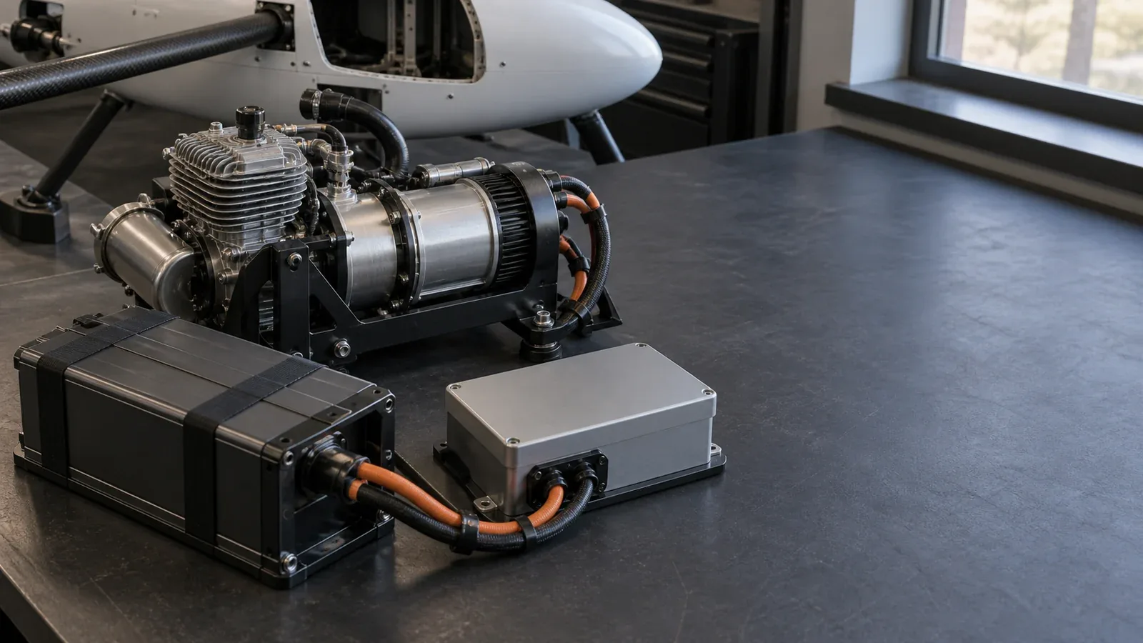
A representative series installation has an engine driving a generator. Power electronics condition its output for a distribution bus, the electrical connection supplying the loads. Motor controllers then regulate electrical delivery to the propulsion motors. A battery connection may include its own converter, depending on the voltage arrangement and charging design.
The conversion hardware does more than connect wires. It must match the required voltage, current, direction of power flow, and motor-control function. NASA's power-converter examples illustrate why specifications belong to a complete installation: some controllers depend on airflow for cooling, while a different bidirectional converter uses circulating dielectric fluid. Those are different integration requirements, even before comparing rated output.
An integrator should therefore identify the following boundaries:
- Generator output to distribution: allowable voltage range and how output is regulated.
- Battery to distribution: permitted charge and discharge current, and who controls each limit.
- Distribution to motor: electrical input limits and the motor controller's command interface.
- Electronics to cooling system: required airflow or coolant conditions throughout the operating envelope.
The aircraft needs a compatible chain at every boundary. A motor's advertised power does not establish that the generator, wiring, battery, controller, and cooling system can supply it together.
How power is shared during a mission
The energy-management controller allocates demand between sources. It can follow rules tied to operating modes or calculate a power split using a model of the remaining mission. Doff-Sotta and colleagues' predictive-control research explicitly constrains battery energy and the operating limits of the engine and electric machine. Its optimization results concern the modeled aircraft, rather than a guaranteed saving for a UAS.
Three operating conditions explain the controller's task:
Demand exceeds generator output. The battery supplies the difference if its discharge limits permit. That can support a short climb or other peak, but it consumes stored energy.
Generator output exceeds demand. Surplus can recharge the battery if the charging path and battery limits allow it. The engine must provide that energy; recharging is not a free endurance gain.
The engine is stopped or unavailable. The battery must supply the remaining electrical loads. Keeping sufficient battery energy becomes a separate mission constraint from carrying enough fuel.
The operating plan must specify the battery state needed at future demanding phases. An energy-management strategy that spends reserve early can leave inadequate power or energy for a later phase, even if its earlier fuel use appears favorable. If demand stays above available generator output, the battery continues to discharge: carrying additional fuel does not eliminate that power deficit.
A worked power and reserve example
Consider an illustrative series hybrid. These are assumed values chosen to explain the arithmetic, not measured aircraft specifications. All powers are referred to the same distribution bus and include propulsion, avionics, payload, and downstream losses. Battery energy is usable energy deliverable at that bus.
Assume a generator can continuously deliver 2.0 kW under the mission conditions. A two-minute high-power segment requires 3.0 kW. The battery must supply 1.0 kW throughout it:
Battery energy used = (3.0 − 2.0) kW × (2 ÷ 60) h = 0.0333 kWh, or about 33 Wh.
If the subsequent load falls to 1.6 kW, the available surplus is 0.4 kW. Assume that 90% of bus energy sent into charging becomes energy deliverable back to the bus. Restoring that energy then takes:
Recharge time = 0.0333 kWh ÷ (0.4 kW × 0.90) = 0.0926 h, or about 5.6 minutes.
That calculation assumes uninterrupted surplus, adequate charging capability, and no additional thermal or operating restrictions. Another high-power segment before recharge completes draws further on the battery.
Now suppose 120 Wh remains deliverable above a protected minimum and a recovery segment requires a steady 2.4 kW with the generator unavailable:
Energy-limited recovery time = 0.120 kWh ÷ 2.4 kW = 0.05 h, or 3 minutes.
Three minutes is the result of these assumptions, not a safe-flight allowance. The battery and its connection must also deliver 2.4 kW immediately. If they cannot, the energy calculation is irrelevant. Actual recovery planning must account for load changes, battery condition, temperature, and the reserve required by the aircraft's operating procedures.
This exposes two separate acceptance questions: can the system supply the required power now, and can it sustain that power for the required time?
Interfaces and failures that matter
The flight controller needs useful power-system information, not merely an engine-running indication. For example, the MAVLink common message set defines GENERATOR_STATUS fields for generated power, bus voltage, battery current, and generator and rectifier temperatures. It also defines reduced-power, overheating, communications, and electrical-fault flags.
Those fields illustrate a concrete interface; their presence in a protocol does not establish that a particular controller transmits them or that an autopilot acts on them. Check message support, update timing, missing-data handling, and the response to each relevant condition. A displayed value that has stopped updating cannot establish current power capability.
Separate loss of generation from loss of the power path
A battery can support propulsion after generation stops only if the remaining electrical path is usable. A short on a shared bus is a different problem from a stopped engine. NASA's fault-management explanation describes distributed protection that detects electrical faults and interrupts affected paths. Its hardware targets address much larger aircraft; the relevant principle here is fault isolation.
The following table is an engineering interpretation of those electrical dependencies and MAVLink's documented condition categories. It describes questions to establish for an aircraft, rather than prescribing emergency actions.
| Condition | What it threatens | What the aircraft design must establish |
|---|---|---|
| Generator stops | Continued generation | Battery power capability and usable time to the intended recovery outcome |
| Generator reduces output | The expected power balance | Detection of the deficit and whether continued operation consumes protected reserve |
| Shared electrical path faults | Delivery from either source | Which section is isolated and which propulsion and control loads remain powered |
| Battery cannot accept charge | Recovery of spent battery energy | Charging limits, indication, and mission consequences |
| Thermal limit is reached | Continued component output | Available power after limiting or shutdown, under the actual cooling conditions |
Two energy sources do not automatically provide two independent propulsion systems. Trace the shared bus, switches, controllers, and cooling dependencies before describing an installation as redundant.
Make the fault response part of the interface
For each fault, establish who detects it, who limits or disconnects power, what information reaches the flight controller, and which operating modes remain possible. In a parallel installation, include the mechanical coupling and the ability to isolate a failed drive element. Electrical backup alone does not establish that a common shaft will remain usable.
Performance tradeoffs and representative applications
Hybridization adds equipment as well as energy options. In a series arrangement, the engine-to-generator-to-motor route includes conversion losses and installed component mass. In a parallel arrangement, mechanical coupling brings a different integration burden. The useful comparison holds the mission, payload, reserves, and operating conditions consistent.
Jimenez and colleagues' 2022 UAV sizing study compared series and parallel distributed-propulsion designs for environmental monitoring. Its modeled Galapagos mission favored a particular parallel arrangement. That finding demonstrates how configuration and mission interact; it does not establish that every parallel hybrid outperforms every series system.
For an environmental survey requiring sustained airborne sensing, compare useful mission time at the specified payload after accounting for the installed propulsion package. For a mission with repeated peaks, inspect battery depletion and the time available between peaks to recover it. These are different design cases, even if their total flight durations match.
Engine-off operation introduces another application. Noise-aware UAV planning research models routes with segments where the generator must remain off, together with battery and fuel constraints. Its practical implication is that route selection and generator scheduling may need to be solved together. An engine-off segment spends battery energy that may also be needed later; switching off combustion does not establish silent flight.
A current experimental example is the XRQ-73. DARPA reported on May 6, 2026 that the aircraft flew at Edwards Air Force Base in April under its Series Hybrid Electric Propulsion AiRcraft Demonstration program. That confirms a flight demonstration. The announcement does not provide a matched endurance or fuel-consumption comparison from which to calculate a general UAS performance improvement.
What to establish before selecting an architecture
Start with the mission's load history and a power-flow diagram. Require continuous generator output under the intended conditions, battery power and usable energy limits, charging capability, and the predicted reserve at each demanding phase. Then examine the same mission with the credible loss of a source or shared component.
Choose a hybrid architecture when that complete comparison shows a useful mission benefit after installed mass, losses, cooling, and recovery requirements are included. A peak-power rating or headline flight time cannot answer whether the aircraft will complete the required mission with the reserve it needs.
Sources
- NASA: Aircraft Configurations. Agency explanation of hybrid and turboelectric power paths; includes the cited series-hybrid illustration.
- NASA: Power Converters. Technical examples connecting converter functions, bus specifications, and cooling arrangements.
- Doff-Sotta, Cannon, and Bacic: Predictive energy management for hybrid electric aircraft propulsion systems. Research manuscript, June 2022 version, on constrained power allocation and battery-energy models.
- MAVLink: Common Message Set. Official protocol definitions for generator telemetry and fault indicators.
- NASA: Circuit Breakers. Agency explanation of electrical fault isolation and thermal-management challenges.
- Jimenez et al.: Evaluation of Series and Parallel Hybrid Propulsion Systems for UAVs Implementing Distributed Propulsion Architectures. Aerospace, 2022, volume 9, article 63; mission-specific conceptual sizing study.
- Noise Aware Path Planning and Power Management of Hybrid Fuel UAVs. Research preprint modeling route and generator scheduling under noise and energy constraints.
- DARPA: XRQ-73 demonstrates hybrid-electric flight. May 6, 2026 program announcement documenting the April flight demonstration.
Last checked: September 6, 2026.