GNSS/INS integration combines a global navigation satellite system (GNSS) with an inertial navigation system (INS) to estimate an unmanned vehicle's position, velocity, and attitude. GNSS supplies an external reference that constrains accumulated error; the INS carries the estimate between satellite updates and during interruptions. The result depends on measurement quality, alignment, timing, and fault handling. NovAtel's GNSS/INS overview explains this complementary relationship.
For an integrator, the central question is how the estimate behaves when inputs become delayed, misleading, or unavailable. A navigation unit that continues sending coordinates has not necessarily retained enough accuracy for the mission.
On This Page
- From sensor measurements to vehicle state
- Choose what the estimator combines
- Make the interfaces describe the same motion
- Initialization and heading need their own requirements
- What happens when navigation degrades
- How the application changes the design
- Evaluate the installed navigation chain
From sensor measurements to vehicle state
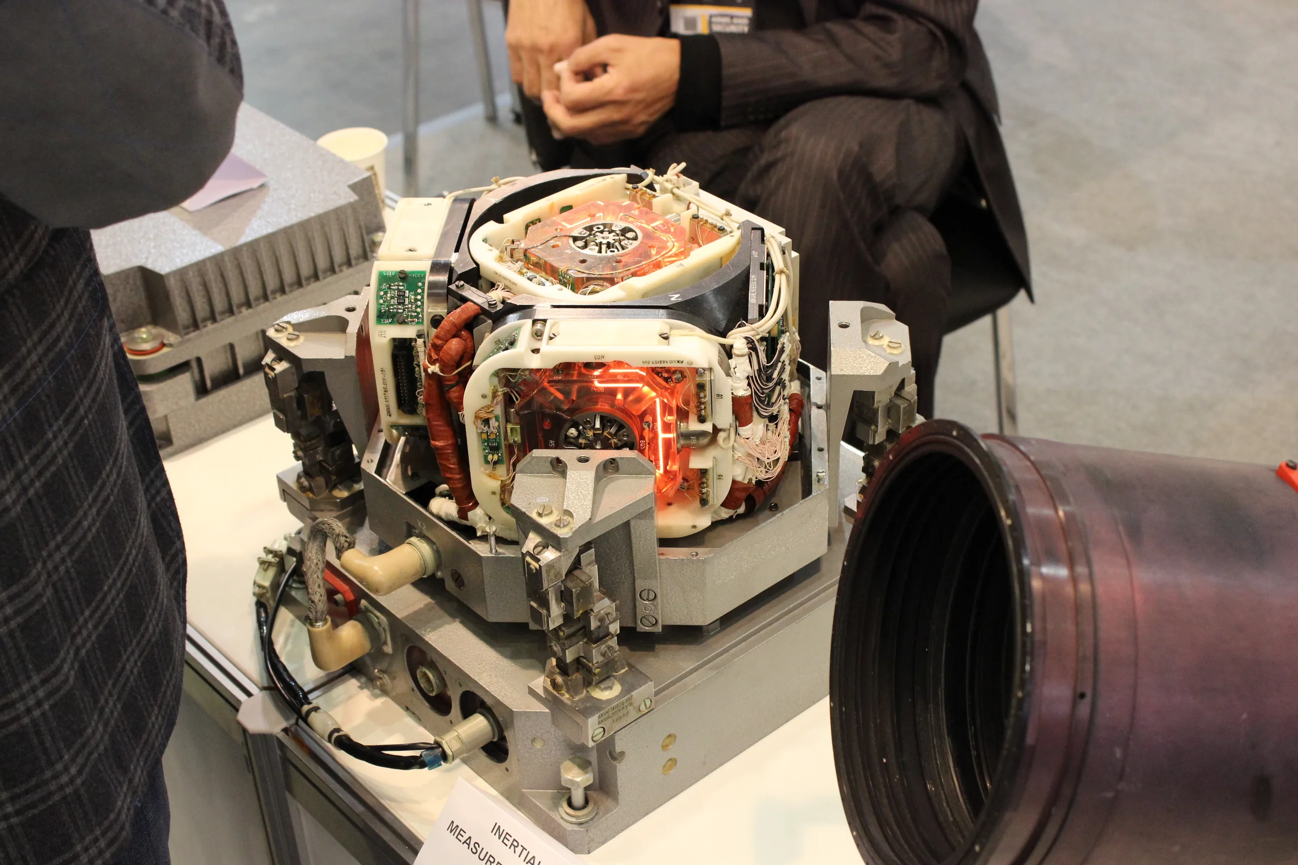
An inertial measurement unit, or IMU, measures angular rate with gyroscopes and specific force with accelerometers. The INS adds the navigation computation. It updates orientation, transforms the accelerometer measurements into the navigation frame, accounts for gravity, and integrates motion into velocity and position. Small sensor and orientation errors therefore propagate into the navigation solution. VectorNav's INS error-budget explanation describes these dependencies.
GNSS observations provide opportunities to correct the inertial estimate. A filter compares an incoming observation with the value predicted from its current state. That difference, often called an innovation, helps update the estimated state and sensor biases according to their modeled uncertainty. The inertial computation then continues from the corrected estimate. NovAtel describes how the external GNSS reference helps estimate and mitigate IMU errors in its integration overview.
The complete system boundary includes antennas, receiver, IMU, estimator, and the consuming controller or mapping system. The broader sensor fusion architecture explains where other observations enter this chain. Keeping that boundary explicit prevents a receiver specification from being mistaken for vehicle-level navigation performance.
Choose what the estimator combines
Coupling describes where GNSS information enters the estimator. It does not rank the quality of complete navigation products.
| Architecture | Information combined with inertial navigation | Integration consequence |
|---|---|---|
| Loosely coupled | Receiver-computed position and velocity | Provides a clear receiver-to-estimator boundary; aiding depends on the receiver supplying usable solution updates. |
| Tightly coupled | Individual satellite observations, such as pseudorange and Doppler | Can retain useful constraints when a complete standalone GNSS fix is unavailable; requires access to observations and their measurement models. |
| Ultra-tightly coupled | Inertial feedback also assists receiver tracking loops | Extends integration inside the receiver, requiring a coordinated tracking and navigation design. |
Source basis: VectorNav's coupling explanation and NovAtel's integration overview. The interface consequences are engineering interpretation of those architectures.
Tight coupling can use partial satellite information, but that does not mean a partial observation independently determines every position component. Nor does deeper coupling make reflected or corrupted signals trustworthy. Outlier rejection and the actual signal environment remain important. VectorNav explicitly cautions that coupling architecture alone does not establish superior performance.
For procurement, ask which observations are available, which the estimator actually uses, and what it reports when they are rejected. A label such as “integrated navigation” is too broad to answer those questions. Also distinguish an onboard estimate used by a controller from a trajectory refined after the mission; a later processing result cannot demonstrate what the controller knew at the time.
Make the interfaces describe the same motion
Time alignment
A measurement timestamp should identify the physical observation time in a known clock domain. Packet arrival time also includes processing, transport, and scheduling delays. Combining an old GNSS observation with a current inertial state can make genuine movement appear to be a disagreement between sensors.
PX4 v1.17 provides a concrete implementation: its estimator buffers measurements and combines them at a delayed fusion time, then propagates the estimate forward using buffered IMU data. Its navigation-filter documentation makes sensor-delay configuration part of integration.
As a simple illustration, assume a vehicle travels in a straight line at a constant 15 m/s and an uncompensated timestamp mismatch is 0.020 s. The positions associated with those two times differ by:
Distance difference = speed × time mismatch = 15 m/s × 0.020 s = 0.30 m.
This is a hypothetical kinematic calculation, not a predicted estimator error or a hardware measurement. Turns and acceleration add further dependencies. It explains why timing deserves a separate check even when the position specification looks sufficient.
Geometry and coordinate frames
The GNSS antenna and IMU normally occupy different physical points. Their displacement is the lever arm. Rotation of the vehicle changes that displacement in the navigation frame, so the estimator needs both the offset and the coordinate convention used to express it.
NovAtel's SPAN installation guidance distinguishes the IMU frame, vehicle frame, and user output frame. It also separates antenna offsets from IMU-to-vehicle rotation and warns that the installation and initialization affect achieved performance.
Record which point the output represents: the IMU, antenna, vehicle origin, or a payload reference. Then verify axis directions, handedness, angle conventions, units, and the height reference at both ends of the interface. A physically rigid installation must preserve the geometry represented in those settings. Check the vibration environment too: NovAtel cautions that damping intended to reduce vibration can also remove actual motion from the measurement.
Messages and uncertainty
Choose a documented device interface and supported driver, then check the message contents independently of the transport. Receiving bytes is only the first step. The consumer needs a defined position and velocity frame, observation time, uncertainty representation, and indication of resets or invalid estimates.
For example, the MAVLink ODOMETRY definition includes separate pose and velocity frame identifiers, a quaternion, covariance arrays, and a reset counter. Its timestamp can use epoch time or time since boot. These fields illustrate the contract that an external navigation interface must resolve; the message definition alone does not establish that a particular autopilot accepts a particular navigation unit.
This is also a component-replacement issue. The discussion of open architecture in unmanned systems explains why interface semantics and documented behavior belong alongside connector and protocol choices.
Initialization and heading need their own requirements
An initial position fix and a fully converged inertial solution are different milestones. NovAtel's SPAN guidance separates initial alignment from the motion needed to converge estimated errors. A vehicle should not be assumed ready for an outage immediately after it first reports a position.
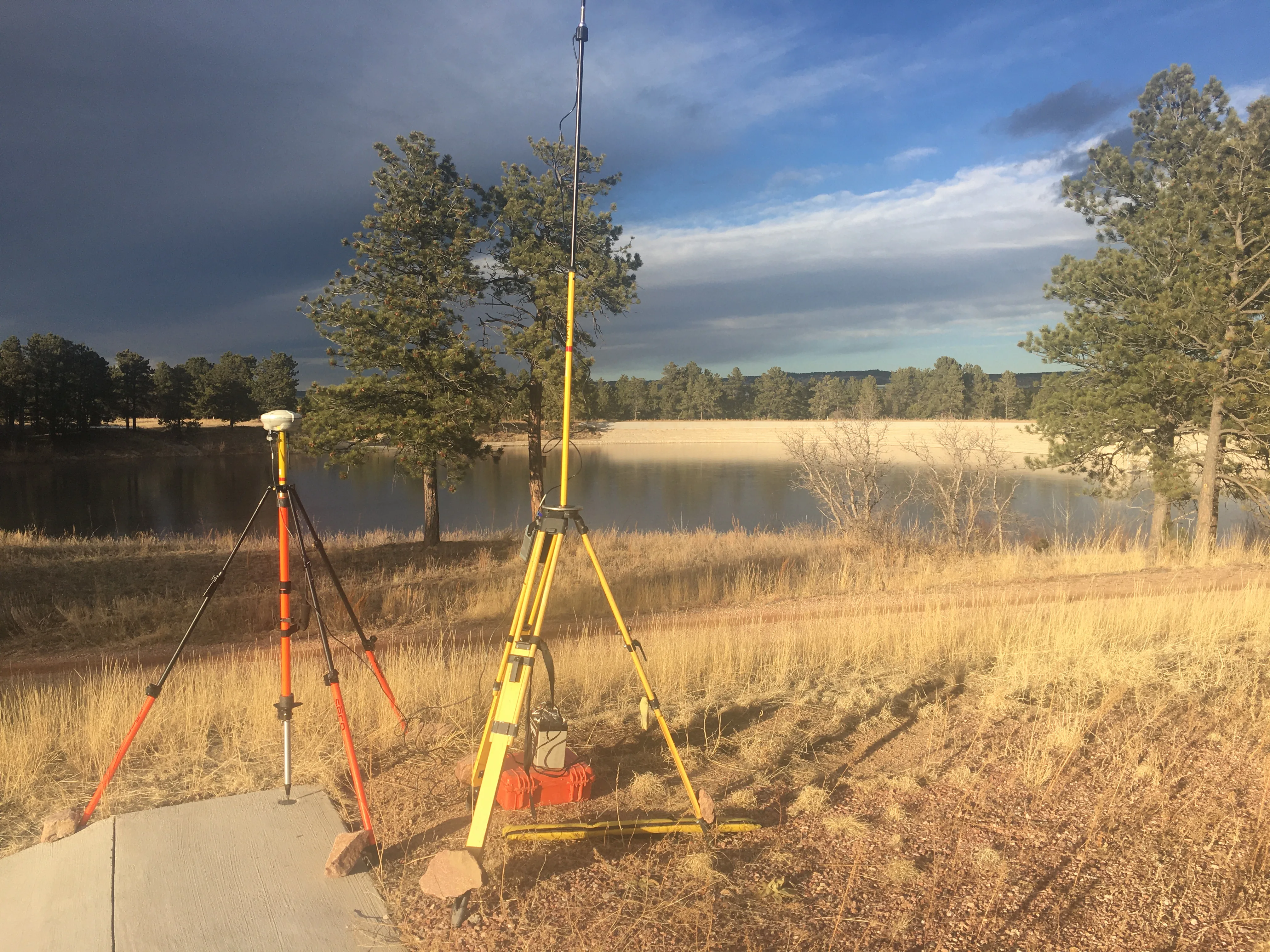
Heading creates an additional constraint for slow or stationary platforms. A GNSS compass uses the measured baseline between two antennas to estimate orientation without requiring vehicle translation. VectorNav's dual-GNSS explanation describes this moving-baseline technique and its dependence on baseline geometry and signal quality.
For a hovering aircraft or a surface vehicle waiting at a waypoint, the practical question is whether heading remains observable during that behavior. Two antennas add mounting space, baseline calibration, and another sky-view requirement. They do not eliminate satellite-signal dependencies. Course over ground describes movement direction and must not be silently substituted for the direction the vehicle faces.
Write startup requirements around the actual platform: available motion, time to usable heading, reported convergence, and behavior after power cycling. Require the supplier to distinguish initial alignment from subsequent refinement.
What happens when navigation degrades
During an unaided interval, residual accelerometer error integrates into velocity and position error; orientation error can also introduce an incorrect gravity contribution. VectorNav's error budget explains why outage error depends on more than one bias specification. An improved GNSS solution before an outage does not remove the subsequent inertial error growth.
There is consequently no universal GNSS/INS accuracy or guaranteed outage duration. Compare candidate specifications only when their initial alignment, aiding, motion, outage length, and reported error statistic match. A high output rate describes how often an estimate arrives; it does not prove its accuracy or freshness.
The following checks are an engineering synthesis of the installation, estimator, and error-budget documentation cited above.
| Observed behavior | Plausible issue to investigate | Useful evidence |
|---|---|---|
| Disagreement increases with speed or turns | Timing mismatch, lever-arm error, or frame rotation error | Observation timestamps, measured offsets, configured rotations, and synchronized trajectories |
| Position exists but stationary heading is unstable | Heading reference is unavailable or insufficiently observed | Heading-source status, antenna baseline solution, startup and stationary logs |
| Error grows while GNSS is absent | Inertial drift and insufficient remaining aiding | Time since last accepted correction, uncertainty, and an independent reference trajectory |
| GNSS is received but not used | Quality or consistency checks reject the observations | Receiver status, estimator innovation tests, and rejection flags |
| The solution changes abruptly after recovery | Reintroduced observations disagree with the propagated state | Reset indicators, time-aligned innovations, and controller response |
PX4's documentation separately describes GNSS quality checks and innovation checks. Those are useful diagnostic distinctions: sensor reception, sensor acceptance, and a usable navigation state are separate events. The checks should inform diagnosis rather than be relaxed simply to make a warning disappear.
Also distinguish loss of signal from misleading observations. Multipath can bias measurements, and intentional interference can compromise GNSS. A fused system should not be presumed immune because it contains an IMU. Define what evidence makes an observation acceptable and what the vehicle does when confidence becomes insufficient.
How the application changes the design
Unmanned aircraft: attitude and motion estimates support the flight controller, while mapping payloads also need position and orientation associated with capture times. Treat payload timing and reference-point geometry as additional interface requirements. PX4's documented state estimation is one implementation example; configuration and supported inputs remain version-specific.
Ground vehicles: wheel-derived motion can add another constraint when satellite reception is interrupted. NovAtel's SPAN odometer documentation describes displacement and velocity inputs that constrain inertial error during GNSS outages. In a vehicle evaluation, include surfaces and maneuvers that challenge the relationship between wheel motion and vehicle motion rather than assuming that relationship always holds.
Surface vehicles: slow motion and heading requirements make antenna-baseline design particularly relevant. Check whether the vessel can perform the initialization motion assumed by its navigation configuration. A solution demonstrated during continuous travel does not by itself answer stationary heading performance.
Underwater vehicles: continuous GNSS aiding is not the submerged operating model. WHOI describes Sentry's navigation system as combining an INS and Doppler velocity log with acoustic navigation. The broader AUV navigation architecture explains how surface fixes, underwater measurements, and mission duration fit together. This is a change in available aiding, not simply an unusually long ordinary GNSS update interval.
For a comparison with camera-based navigation, the visual-inertial odometry guide develops the timing, calibration, interface, and loss-of-tracking questions to include in an integration evaluation.
Evaluate the installed navigation chain
Start with the mission's permissible position, velocity, heading, and latency errors. State which must remain within limits during degraded operation and for how long. Then evaluate the complete path from physical measurements to the consumer's behavior.
- Inspect the interface contract. Identify measurements, clock domains, frames, output reference point, uncertainty fields, and reset behavior.
- Verify the installed geometry and startup. Record antenna and IMU placement, calibration assumptions, alignment, and convergence under motion the vehicle can actually perform.
- Compare matched operating conditions. Separate open-sky operation, partial obstruction, loss of aiding, and recovery. Include the remaining aiding sources in every result.
- Observe degraded behavior. Use controlled simulation, recorded-data replay, and appropriately contained trials to examine rejection, uncertainty growth, and controller response. Do not equate continuous output with continued mission capability.
- Retain diagnostic data. Keep the observations, configuration, timing, status, and independent reference needed to explain a discrepancy.
The resulting decision should identify which measurements keep the required states observable, how long the installed system can tolerate their loss, and how the vehicle recognizes that its navigation limit has been reached. That is the useful meaning of successful GNSS/INS integration.
Sources
- NovAtel: SPAN Overview and Integration Guide. Manufacturer application note APN-109; pages 4–5 explain complementary measurements, filter corrections, and integration architectures.
- VectorNav: GNSS-Aided Inertial Navigation System. Manufacturer primer on coupling, measurement rejection, and signal limitations.
- VectorNav: INS Error Budget. Analytical treatment of inertial error propagation; simplified models are not installed-system guarantees.
- NovAtel: SPAN Data Collection Recommendations. APN-080 in Waypoint documentation, D100515 v6, April 2026; installation frames, lever arms, initialization, and convergence.
- PX4 v1.17: Using PX4's Navigation Filter. Official software documentation for state estimation, delays, and measurement checks.
- MAVLink: Common Message Set, ODOMETRY. Official protocol definition for navigation state, frames, time, uncertainty, and resets.
- VectorNav: GNSS Compass/INS. Manufacturer explanation of antenna-baseline heading and its dependencies.
- NovAtel: SPAN Installation and Operation Manual. Manufacturer manual, section 3.8: distance-measurement instruments, displacement updates, and velocity inputs for ground-vehicle aiding.
- Woods Hole Oceanographic Institution: Sentry. Operator description of an AUV using inertial, Doppler, and acoustic navigation.
Last checked: September 8, 2026.