A battery management system (BMS) monitors a rechargeable battery pack, manages cell limits, and reports information that helps an unmanned vehicle use its remaining energy. It connects electrical measurements to protective actions and vehicle decisions. A useful design must answer both whether the battery can supply the next maneuver and whether enough energy remains to finish or recover.
The distinction matters across aircraft, ground robots, and marine vehicles. A healthy-looking pack percentage cannot establish that every cell is within limits, that the requested current is available, or that the vehicle can reach safety. Those questions belong to different parts of the power and control architecture.
On This Page
- Where the BMS fits
- How measurements become battery estimates
- What cell balancing changes
- Define the vehicle interface
- Handle failures before recovery becomes impossible
- Match the design to the mission
- Evaluate the complete power system
Where the BMS fits
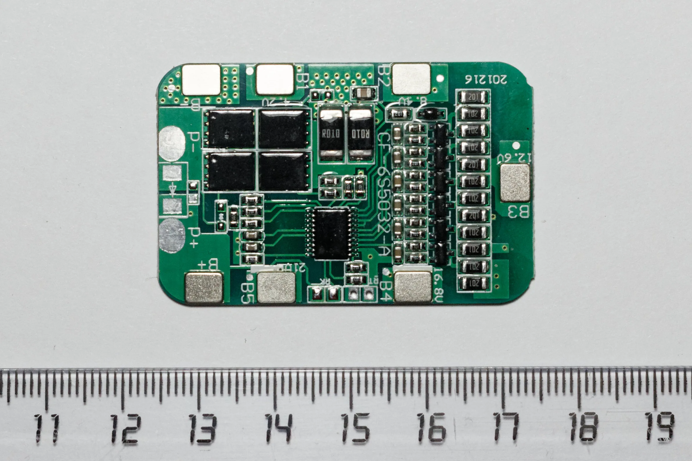
A typical pack combines cell-voltage sensing, pack-current measurement, temperature sensors, monitoring electronics, and a controller. Depending on the design, it can also include balancing circuits and switches that interrupt charging or discharging. The charger supplies controlled charging power; the BMS supervises battery conditions. The vehicle controller decides what a warning or reduced power allowance means for the mission. A voltage-and-current monitor connected to an autopilot should not be assumed to provide all these pack-level functions.
Texas Instruments' BQ76952 data sheet illustrates the monitoring layer: cell measurements, current sensing, thermistor inputs, configurable protection, balancing, and host communications. An integrated monitor is one building block, not a complete vehicle energy-management system.
In a centralized arrangement, sensing connections converge on one main assembly. A modular arrangement places monitoring electronics with groups of cells and communicates their measurements to a supervising controller. NXP's flexible BMS reference design demonstrates how these approaches can be mixed, with local cell controllers, isolated communications, and linked boards.
For an integrator, the choice changes wiring, service access, and fault isolation. A compact pack may favor fewer assemblies; a physically divided pack may favor local measurement and module replacement. Distributed sensing also creates more communication and startup dependencies. Ask which measurements and protective functions remain available if one module stops responding. The architecture's name alone does not establish fault tolerance.
How measurements become battery estimates
State of charge (SOC) expresses remaining charge relative to a defined capacity. A state of health (SOH) report needs a separate definition: ask whether it describes retained capacity, resistance, or another measure of degradation against a reference. Do not compare health percentages until their definitions match.
A voltage reading is a measurement; remaining charge is an estimate. Under load, battery terminal voltage falls. When the load is removed, voltage can recover without any recharge. PX4's battery-estimation guide describes progressively combining raw voltage, load compensation, and measured current consumption. It also requires calibration of the voltage and current measurement paths.
Coulomb counting integrates current over time to track charge entering or leaving the pack. It depends on an initial charge estimate and accurate current measurement. Voltage observations and battery models can help anchor that estimate. TI's Impedance Track application note explains one implementation that combines chemistry, resistance, load, and temperature, including relaxed-voltage observations. Its single-cell implementation is an example of the method, not a universal algorithm for unmanned vehicles.
Usable capacity also depends on the operating condition. TI explains that higher discharge rates and low temperature can cause the termination voltage to be reached earlier. A pack may therefore retain charge while being unable to support the required load within its limits.
Consider a proposed return maneuver that demands more current than routine cruising. The integration question is whether the remaining pack can support that maneuver at its present temperature and condition. Reserve planning should check both energy to complete recovery and power available during recovery. A charge percentage alone answers neither completely. Record the duration of any permitted peak load as well as its magnitude; a brief current allowance should not be treated as a continuous rating.
What cell balancing changes
Cells in a series string do not retain identical capacity and behavior throughout their lives. One cell can reach a limiting condition while others still have usable charge. Monitoring only total pack voltage can conceal that difference.
Passive balancing removes charge from selected cells through resistive paths, dissipating energy as heat. Analog Devices' cell-balancing explanation describes how this reduces differences in charge state. It does not restore the capacity of a degraded cell.
Active balancing transfers charge between cells or between cells and the stack. Analog Devices' active-balancing article describes the additional circuitry and potential to make more stored charge usable. The benefit depends on the imbalance, transfer capability, and operating cycle; it is not a fixed endurance improvement for every pack.
Compare the actual balancing window. If the vehicle spends little time charging or resting in a state where balancing operates, a headline balancing-current specification may say little about daily operation. Ask when balancing runs, what stops it, how its heat is handled, and how persistent imbalance leads to maintenance. Treat recurring imbalance as a condition to investigate, rather than something stronger balancing automatically cures.
Define the vehicle interface
The electrical connection and the information contract are separate. A CAN connection specifies a communication technology, but the receiver still needs the correct messages, identifiers, units, timing, and fault meanings. Internal chip interfaces such as I2C or SPI also should not be confused with the vehicle's external battery interface. NXP's reference design illustrates separate cell-monitoring links and a CAN interface.
MAVLink's battery protocol provides a concrete reporting example. Battery status is reported for individual batteries with instance identifiers. The guide warns that aggregate state across multiple batteries is not standardized, and that legacy system-status fields can depend on the flight stack's configuration. Two displayed packs do not establish how they share propulsion loads or fail over.
Use the following questions to turn a telemetry specification into an integration agreement. They are engineering review questions based on the NXP and MAVLink documentation, rather than additional protocol requirements.
| Information crossing the boundary | Question to resolve | Why it matters |
|---|---|---|
| Pack and cell measurements | Which values are measured, estimated, absent, or invalid? | A missing sensor must not look like a safe zero reading. |
| Battery identity and charge state | Which physical pack and capacity definition does each value describe? | Swapped packs and multiple sources need unambiguous records. |
| Charge and discharge limits | Does the vehicle receive limits, and which controller enforces them? | Reporting a restriction is insufficient if the load continues unchanged. |
| Faults and message freshness | What happens after a timeout, restart, or latched fault? | Previously valid data must not remain trusted indefinitely. |
Include charger behavior in the same review: permitted charging conditions, stop requests, completion, and recovery after interruption. The publication's guide to open architecture in unmanned systems explains why substituting a component requires agreement on behavior as well as connectors.
Handle failures before recovery becomes impossible
Cell protection and vehicle recovery operate at different levels. A protection circuit may disconnect a battery to enforce an electrical limit. An airborne vehicle also needs power to remain controllable. Design the warning and recovery strategy around the actual protective behavior, with enough margin to act before a foreseeable limit is reached. Do not assume a planned return can succeed after its power source has disconnected.
PX4's failsafe documentation separates configurable battery warning, critical, and emergency levels and describes a remaining-flight-time check for return. These are software-specific examples of staged responses. They do not prescribe universal thresholds or certify a battery installation.
The following fault review combines the TI monitor's documented diagnostics with PX4 and MAVLink behavior. The checks are proposed integration work, not reported test results.
| Failure or misleading indication | Possible consequence | What to demonstrate |
|---|---|---|
| Cell-sense connection fails | A cell reading becomes unreliable. | Detection, invalid-data reporting, and the selected response. |
| Current measurement is biased | Consumed-charge estimation drifts. | Calibration and comparison with an independent measurement over a representative duty cycle. |
| Battery messages stop | The controller may retain an obsolete estimate. | Timeout handling and recovery after communications resume. |
| Temperature input fails | Charging or load decisions lose a necessary input. | Sensor-fault identification and behavior without a valid reading. |
| Pack disconnects or controller restarts | Essential loads may lose power or state. | Which functions remain supplied and how restart is controlled. |
A component's detection feature does not establish complete protection against every battery failure. Review sensor placement, wiring, power paths, and fault response together. Otherwise a well-instrumented pack can still leave an essential controller without usable information or power.
Match the design to the mission
The same integration questions lead to different priorities in different vehicles. These examples are application-specific design implications, not performance claims for named platforms.
For a multirotor, review the load during takeoff, maneuvering, and landing, including recovery late in the mission. For a ground robot, examine prolonged low-speed work, charger transitions, and what remains powered during a controlled stop. For an underwater vehicle, establish what the onboard controller can decide without waiting for an operator and which energy-dependent actions its recovery plan requires.
Hybrid power sources need explicit boundaries too. In a fuel-cell aircraft, ask how battery limits constrain the shared power system and which controller manages the buffer battery. The guide to hydrogen fuel cells for long-endurance drones develops the surrounding hybrid architecture.
A tether does not eliminate battery-management questions when a backup pack is installed. Verify its readiness and the transition from tether power to onboard energy. The tethered-drone power guide covers that supply boundary and its operating implications.
Evaluate the complete power system
Begin with the cell chemistry, series arrangement, required load profile, charging method, environment, and recovery maneuver. Then require an interface definition and a demonstration using those conditions. Ask for synchronized cell voltage, current, temperature, estimated charge, fault, and vehicle-action records so that a limit can be traced to the response it caused.
Compare measurement quality, protective response, balancing opportunities, sleep consumption, wiring burden, and serviceability as separate tradeoffs. A more complex estimator requires appropriate characterization and configuration; more distributed hardware requires dependable communication; more balancing capability adds circuitry and thermal considerations. Select the combination that meets the mission rather than the longest feature list.
The decisive result is a vehicle that recognizes a shrinking power margin and takes a feasible action while it still can. Judge the BMS together with the charger, power distribution, and controller that turn its measurements into that behavior.
Sources
- Texas Instruments: BQ76952 data sheet, revision B: manufacturer documentation for monitoring, protection, diagnostics, and host interfaces.
- NXP: Flexible Battery Management System (BMS) Reference Design: an example of mixed centralized and distributed monitoring architecture.
- Texas Instruments: Impedance Track algorithm, revision A: a specific fuel-gauge implementation and the effects of load, resistance, and temperature.
- Analog Devices: Active Battery Cell Balancing: passive charge dissipation, active charge redistribution, and implementation tradeoffs.
- PX4: Battery Estimation Tuning: voltage and current estimation methods and calibration.
- MAVLink: Battery Protocol: individual battery reporting and multi-battery limitations.
- PX4: Safety Configuration: configurable battery responses and return-time checks. PX4 links reference the evolving main documentation; verify behavior against the installed release.
Last checked: September 9, 2026.