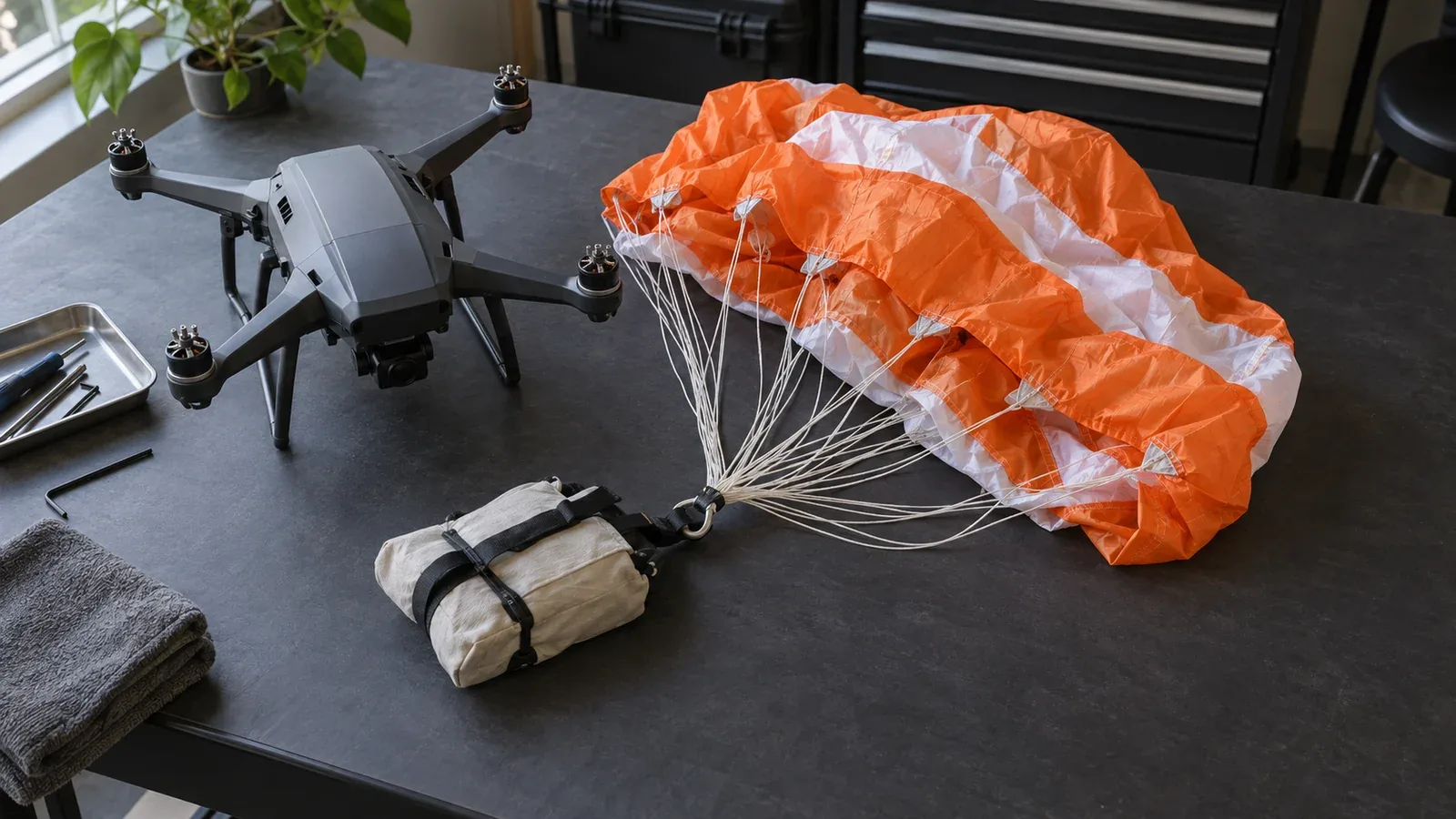
A drone parachute recovery system slows an aircraft's descent by deploying a canopy and transferring its aerodynamic drag through lines and a harness into the airframe. The complete system also needs a way to recognize an emergency, authorize deployment, stop propulsion where required, and release the parachute while enough height remains for it to work.
The decisive question is whether that entire chain works for the aircraft's failure conditions. A canopy's steady descent rating applies after inflation; it cannot establish how an installation behaves during the preceding power failure, tumble, or low-altitude release. Parachute recovery can reduce consequences, but it does not guarantee an undamaged aircraft or a harmless landing.
On This Page
- Follow the recovery sequence
- Connect the system without sharing every failure
- Understand height, descent speed, and drift
- Review failures before choosing settings
- Match recovery to the application
- Separate a standard from operational permission
- Ask for a complete installation demonstration
Follow the recovery sequence
Think of recovery as a sequence of physical events: detection, command, release, extraction, inflation, deceleration, and touchdown. A deployment message confirms only part of that sequence. The following is an engineering breakdown of the functions described in the cited autopilot and recovery-system documentation.
| Function | Input and output | Integration question |
|---|---|---|
| Detection and arming | Flight measurements and readiness conditions become an emergency decision | Which failures can the detector recognize, and when is it inhibited? |
| Triggering | An automatic decision or manual command becomes an electrical release signal | Does the signal reach the actuator after the initiating fault? |
| Propulsion termination | A termination request removes the intended propulsion output | Can the aircraft still drive its propellers through the deployment path? |
| Extraction and inflation | A released package becomes an inflated canopy | Does the launcher clear the aircraft in the tested attitudes? |
| Load transfer | Canopy drag passes through lines, harness, and attachment points | Can the installed structure carry the opening load? |
| Descent and retrieval | The suspended aircraft reaches the surface | Where can it land, and what inspection follows? |
The extraction mechanism matters. Fruity Chutes' integration guide distinguishes active launchers, such as spring or compressed-gas systems, from passive extraction using a smaller drogue parachute. An active launcher supplies separation from the aircraft. Passive extraction depends on suitable airflow and geometry, which makes the aircraft's attitude and forward motion important.
The same guide identifies propeller entanglement and deployment direction as integration concerns. Mounting a launcher where it fits is insufficient: its exit path and the loaded harness must suit the airframe. Added equipment also consumes mass and installation volume. Compare the complete installed assembly, including mounts and triggering hardware, rather than only the packed canopy.
Connect the system without sharing every failure
There are two different questions about independence: can the parachute decide to deploy, and can it supply the energy to deploy after the aircraft fails?
PX4's parachute documentation describes PWM and MAVLink connections associated with flight termination. It also states that a PX4-dependent release requires a powered, functioning flight controller unless another system triggers deployment independently. A second output on the same failed controller does not solve that dependency.
An independent detector and battery can address different parts of the problem. As one documented architecture example, the AVSS PRS-M350 manual, version 1.2, describes autonomous and manual triggering, a flight termination system, and an independently powered electronics module. That is a description of this installation, not proof that any separately selected detector, launcher, and aircraft are compatible.
Draw the actual power and command paths. Identify shared regulators, connectors, processors, and wiring routes. For a ground-connected aircraft, include the ground equipment in that drawing; the tethered-drone power and data guide walks through those interfaces and loss-of-power questions. Ask what happens when the flight controller stops, the propulsion battery disconnects, or the recovery battery is depleted. The publication's battery-management explanation provides context for distinguishing reported charge from available power and protection behavior.
Electrical compatibility includes startup behavior. ArduPilot's parachute guide supports relay or PWM triggering and warns that GPIO outputs are low during the bootloader period. The prescribed release polarity and initialization settings therefore matter. A connector that physically fits does not establish a safe resting state, adequate actuator power, or a valid release pulse.
Document the installed firmware versions and the meaning of every readiness indication. Check which conditions prevent arming and what the operator sees if the recovery device is missing. Separate electronic readiness from mechanical inspection: a communications heartbeat cannot confirm the condition of the packed canopy or harness.
Understand height, descent speed, and drift
Minimum deployment height is an installation limit. Height is consumed while detecting the fault, issuing the command, extracting the canopy, inflating it, and reducing descent speed. The aircraft's initial downward velocity and attitude change that sequence. PX4 specifically notes that inverted deployment can increase the time needed to slow down and can collapse the canopy.
A software altitude threshold is a different quantity. ArduPilot documents CHUTE_ALT_MIN relative to HOME when loss of control is first detected, and notes that actual release can occur lower during a fast descent. A HOME-relative threshold is not the same as clearance above the ground beneath the aircraft. It cannot replace demonstrated parachute performance. Ask which altitude reference the flight software uses and how the route's terrain affects the available clearance.
Once descent stabilizes, canopy drag balances weight. From NASA Glenn's drag and falling-object explanation, the corresponding idealized relationship is:
Steady descent speed = square root of [2 × mass × gravitational acceleration ÷ (air density × drag coefficient × reference area)].
Mass is in kilograms, area in square metres, and density in kilograms per cubic metre, giving speed in metres per second. The drag coefficient must use the same area convention as the data. This relationship explains why a heavier suspended load or lower air density increases descent speed when other terms stay constant. It does not predict inflation time, opening shock, or a tumbling aircraft's trajectory.
A lower descent speed also means more time aloft after inflation. For a deliberately simplified drift example, assume 60 metres of remaining height, constant vertical descent at 5 metres per second, and constant horizontal wind of 4 metres per second. Descent time is 60 ÷ 5 = 12 seconds; idealized wind displacement is 4 × 12 = 48 metres. These are hypothetical inputs, not a product rating or an operational buffer. The example ignores initial horizontal motion, opening dynamics, gusts, and changing wind with height.
Compare descent performance with the landing area and retrieval access. A slower landing can be useful while still carrying the aircraft beyond a narrow site boundary.
Review failures before choosing settings
Use a failure review to turn broad claims of redundancy into testable questions. These are engineering review cases, not instructions to introduce faults during routine flight.
| Failure or mismatch | What to establish before operation |
|---|---|
| Aircraft power or flight computer fails | Which detection, release, and termination functions remain available? |
| Normal maneuver resembles a fault | Has the detector been assessed across the intended flight modes? |
| Aircraft falls below the effective envelope | What residual risk remains during takeoff, landing, and low-level work? |
| Launch path or harness is obstructed | Is clearance demonstrated with the actual payload and installation? |
| Device reports ready but has degraded mechanically | Which inspection detects packing, connector, or harness damage? |
| Canopy opens but landing is outside the site | Does the recovery plan account for drift and inaccessible terrain? |
Detection deserves particular attention. ArduPilot describes automatic release conditions involving vehicle state, attitude error, barometric behavior, and a sustained detection period. That logic does not amount to detection of every possible aircraft failure. The sensor-fusion guide explains the broader importance of measurement validity and interpretation when combining flight observations.
Servicing is part of readiness. The cited AVSS manual distinguishes its reusable electronics from a single-use parachute pod and specifies inspection, charging, storage, and repacking requirements. Use the applicable current instructions for the installed unit; do not assume that an unused system can remain serviceable indefinitely or that every deployed canopy may be repacked locally.
Match recovery to the application
For an inspection multirotor, the engineering priority may be emergency consequence reduction after loss of controlled flight. Evaluate whether the proposed mission leaves sufficient deployment height and whether a descending aircraft can reach people, equipment, or traffic outside the immediate work area. A parachute does not remove those site questions.
For a fixed-wing mapping aircraft, parachute recovery can also be a planned landing method. Aeromao's Aeromapper Talon page describes optional parachute recovery alongside automatic belly landing. Routine recovery changes the comparison: include servicing between flights, landing-surface suitability, payload protection, and retrieval effort. Do not transfer an emergency-only system's operating assumptions to repeated normal landings.
For a hybrid VTOL aircraft, examine both hovering and wingborne conditions. Fruity Chutes discusses propulsion clearance and forward-flight dependence when considering extraction methods for VTOL. A successful release in one flight regime does not establish behavior through a transition or after an attitude upset. Ask for the tested envelope by regime rather than a single unqualified minimum-height number.
Separate a standard from operational permission
ASTM F3322-24a, listed as active when checked, addresses design, fabrication, and testing of small-UAS parachute recovery systems intended to reduce impact energy following loss of stable flight. Its public scope says compliance is intended to support an application for permission to fly over people. It also directs users to the relevant aviation authority about acceptable use as a means of compliance.
That distinction matters when reviewing a supplier's claim. Ask which standard edition, aircraft configuration, installation, and test report the claim covers. A component label alone does not describe the whole installed aircraft or authorize the intended operation.
For the United States, the FAA's operations-over-people overview describes category-specific aircraft eligibility and operating conditions. Adding a parachute does not by itself satisfy those conditions. Verify the applicable aircraft documentation and operational requirements separately; this article does not establish approval for either product example.
Ask for a complete installation demonstration
Before accepting a recovery system, request a package that identifies the aircraft and payload, installed mass, mounting arrangement, software configuration, detection logic, power dependencies, and tested deployment envelope. Require the demonstration plan to connect the initiating fault to canopy inflation and the resulting descent, rather than ending at an electrical release indication.
Use simulation, functional checks with deployment safely inhibited, and controlled trials as appropriate to the hazard and the manufacturer's test procedure. Agree in advance how tests protect personnel and how the evidence applies to the intended operating conditions. Ask what changes require reassessment, especially payload, mounting, firmware, and battery changes. The UAS airworthiness guide explains the role of configuration control and continued safety.
Choose the installation whose documented recovery envelope fits the mission, whose critical functions remain available after the failures of concern, and whose servicing requirements the operator can sustain. Those conditions make a parachute a usable recovery capability.
Sources
- ArduPilot: Parachute. Flight-controller documentation for release interfaces, initialization, detection, and altitude logic.
- PX4: Parachute. Main-branch documentation for termination interfaces and controller, packing, and attitude limitations; verify the installed release.
- Fruity Chutes: Integrating a Drone Parachute. Manufacturer explanation of extraction methods and installation tradeoffs.
- AVSS: PRS-M350 User Manual, version 1.2. December 2023 installation example covering triggering, independent power, and maintenance; not a claim of current product approval.
- NASA Glenn: Falling Object with Air Resistance. Drag and terminal-velocity relationships; no aircraft-specific performance rating.
- Aeromao: Aeromapper Talon. Manufacturer description of parachute and belly-landing options.
- ASTM International: F3322. Public scope and active edition listing; the full paid specification was not used.
- FAA: Operations Over People General Overview. U.S. category and operating framework, distinct from parachute-system conformity.
Last checked: September 10, 2026.