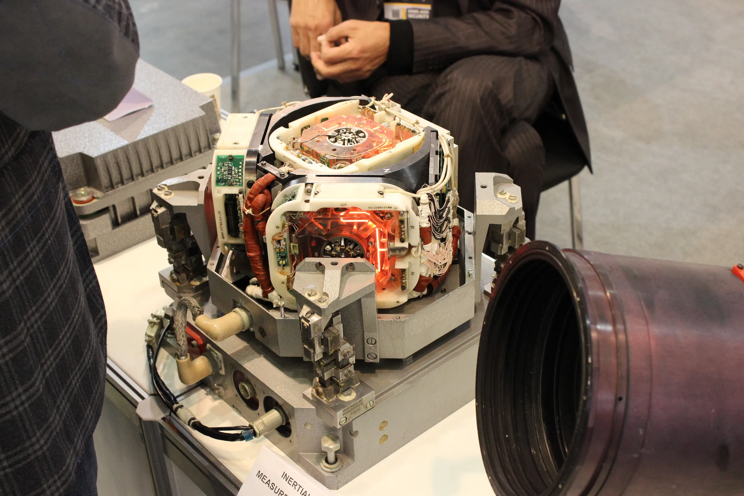
An inertial measurement unit (IMU) measures rotation and specific force. Small errors in those measurements accumulate when navigation software integrates them into orientation, velocity, and position. Calibration reduces repeatable errors such as offsets, scale factors, and axis misalignment; it cannot eliminate random noise or guarantee drift-free navigation. The practical task is to identify which error is growing, correct its cause, and provide suitable measurements to constrain the remaining drift.
For an unmanned vehicle, a successful stationary calibration is only the beginning. The installed sensor must also behave correctly during warm-up, vibration, turns, and interruptions to satellite or visual aiding.
On This Page
- Where the IMU fits in the navigation system
- Separate the errors before correcting them
- How small errors become position drift
- What each calibration actually establishes
- Check the interface as carefully as the sensor
- Diagnose drift under representative conditions
- Match the remaining error to the mission
Where the IMU fits in the navigation system
A typical six-axis IMU combines three gyroscope axes and three accelerometer axes. In microelectromechanical systems (MEMS), an accelerometer senses the displacement of a suspended mass. A vibrating MEMS gyroscope detects motion associated with the Coriolis effect when the device rotates. These are different sensing mechanisms, even when their outputs share one package. VectorNav's MEMS explanation describes both.
An accelerometer does not directly report vehicle acceleration in map coordinates. It measures specific force: a stationary supported sensor has a gravity-related reading, while an ideal sensor in free fall reads zero. Navigation software must rotate measurements into the navigation frame and account for gravity before integrating acceleration.
The processing chain is therefore sensor measurements, calibration corrections, coordinate transformations, inertial integration, and aiding updates. An inertial navigation system (INS) estimates motion from the IMU. Establish whether the application receives sensor readings or an already processed navigation estimate before applying further corrections.
OpenVINS' propagation documentation shows how orientation, velocity, position, biases, and uncertainty evolve together. An error in orientation changes how acceleration is interpreted, so the gyroscope and accelerometer error budgets cannot be treated as unrelated.
External observations, such as satellite position or camera features, constrain the evolving estimate. The broader sensor fusion architecture explains how these measurements enter a vehicle's estimation system.
Separate the errors before correcting them
The word “drift” often combines several problems that need different remedies.
| Error | What it means | Consequence for calibration |
|---|---|---|
| Bias | An additive offset in a sensor output | Estimate and subtract the offset under defined conditions |
| Turn-on repeatability | The initial bias differs between starts | A previous startup's offset may not describe this startup |
| In-run bias instability | Bias changes during operation | One constant subtraction cannot track every change |
| Scale-factor error | Output changes by the wrong proportion of the input | Use known inputs across the required range |
| Axis error | Motion on one axis leaks into another or the assembly is misaligned | Distinguish internal sensor geometry from mounting alignment |
| Temperature dependence | Sensor corrections change with temperature | Characterize the relevant temperature range |
Source basis: VectorNav's IMU specification definitions. The last column translates those definitions into calibration implications.
Noise adds a separate limitation. Angle random walk describes the angular uncertainty produced by integrating gyroscope noise. It is not the same quantity as a constant gyro bias expressed in degrees per hour.
Software parameter names can complicate this distinction. In Kalibr's noise model, gyroscope_random_walk describes changes in the bias itself. It is not a field into which a manufacturer's angle-random-walk number can be copied unchanged.
Allan deviation characterizes noise over different averaging intervals using recorded data. It helps distinguish fast fluctuations from slower bias behavior. A longer average is not automatically a better offset estimate indefinitely, and a quiet stationary recording does not characterize the complete moving vehicle. Use the model, units, filtering assumptions, and data conditions expected by the estimator.
How small errors become position drift
Consider a deliberately simplified, unaided, single-axis example with perfect initial alignment, zero initial velocity error, constant residual bias, and no other errors. These are illustrative inputs, not specifications for a named IMU.
For a residual accelerometer bias of 0.01 m/s², velocity error grows as bias × time. Position error grows as one-half × bias × time²:
Position error = 0.5 × 0.01 m/s² × (60 s)² = 18 m.
At 10 seconds, the same calculation gives 0.5 m. This is why an acceptable short stationary demonstration cannot establish a minute of unaided positioning accuracy.
For a constant gyro bias of 0.01°/s, the corresponding single-axis angle error after 60 seconds is 0.6°. A growing tilt error also projects gravity into the wrong direction, creating additional acceleration and position errors. These examples are separate; adding their results would not produce a valid full navigation prediction. VectorNav's INS error budget explains the integration and coupling.
A real outage analysis must include starting uncertainty, changing biases, motion, aiding that remains available, and the estimator's behavior. A published bias-instability value alone is not a navigation drift rate.
What each calibration actually establishes
Static offsets and known-input calibration
A stationary gyro measurement can support offset estimation when the reference motion is known. Precision work must account for Earth's rotation; “stationary on the bench” is not exactly zero angular rate relative to an inertial frame.
Accelerometers need known gravity directions rather than an assumption that every axis should read zero. A tumble test places the axes in multiple orientations relative to gravity. Gyroscope scale-factor calibration uses known angular rates, commonly from a rate table. VectorNav's calibration guide distinguishes these procedures from noise characterization and recommends independent data for checking the resulting correction.
A useful correction model subtracts a bias vector and applies scale and misalignment corrections. Verify whether the device already applies factory corrections before introducing another correction in the driver or estimator.
Temperature compensation
Temperature compensation measures repeatable changes over a temperature range, fits a correction, and applies it using the sensor's measured temperature. PX4's thermal-calibration documentation gives an implementation example with polynomial offsets and defined temperature limits.
Follow the procedure for the actual hardware and firmware. Do not extrapolate a room-temperature offset into an unmeasured cold start or assume a thermal curve remains valid beyond its documented range. Record the sensor identity, temperature range, correction parameters, and software version together. Verification should include another warm-up cycle rather than only the data used to fit the curve.
Installed geometry and online estimation
Intrinsic calibration describes the sensor itself. Extrinsic calibration describes its rotation and displacement relative to the vehicle, camera, or other sensor. Moving a camera bracket changes the latter even if the IMU's intrinsic corrections remain sound.
Kalibr's camera-IMU procedure estimates spatial and temporal relationships and calls for motion that excites the sensor axes. For the surrounding application, see visual-inertial odometry.
Online bias estimation can track residual error, but only where motion and observations make it distinguishable. OpenVINS warns that restricted trajectories, including planar or single-axis motion, can undermine estimation of additional intrinsic calibration parameters. Enabling more estimated parameters does not automatically improve accuracy.
Check the interface as carefully as the sensor
The data connection must preserve measurement meaning. As a concrete example, the ADIS16505 Rev. C data sheet describes a serial peripheral interface (SPI), data-ready signaling, measurement registers, and diagnostic status. This illustrates a component interface, not a claim that another IMU shares its protocol.
For the installed system, document:
- Units and scale conversions, including degrees versus radians and g versus m/s².
- Axis directions, handedness, and the transformation into the vehicle frame.
- Whether values are instantaneous rates, filtered samples, or integrated increments.
- The measurement timestamp, integration interval, dropped-sample handling, and sensor identity.
- Which layer applies factory, thermal, and user corrections.
Separate sampling frequency from usable bandwidth and latency. More output samples do not prove that the underlying measurements respond faster. Strong filtering may reduce noise while delaying information needed by a controller.
Camera and IMU measurements also need consistent clocks. Kalibr specifically warns about timestamp jitter and buffered delivery that distorts sample spacing. Correcting a fixed time offset cannot recover missing samples or repair arbitrary timing variation. Check acquisition times separately from the time a message reaches application software.
Diagnose drift under representative conditions
Begin with a reproducible symptom: drifting heading at rest, a position error that grows through an outage, or a height estimate that fails only with motors running. Preserve raw sensor data, temperatures, timestamps, correction settings, and estimator innovations. An innovation is the difference between a predicted measurement and the observation used to correct it.
The following diagnostic sequence is an engineering synthesis of the PX4, Kalibr, and Analog Devices references, not a universal maintenance procedure.
| Observed pattern | First question to resolve | Useful comparison |
|---|---|---|
| Offset changes through warm-up | Does the correction cover this temperature cycle? | Raw and corrected data against temperature |
| Failure appears during motor operation | Is vibration causing clipping, aliasing, or a shifted output? | Sensor range, vibration records, and innovations |
| Error appears mainly during turns | Are axes, mounting transforms, and timestamps consistent? | Known direction of rotation against all reported axes |
| Calibration works once but fails after restart | Did sensor selection or the startup bias change? | Device IDs, saved parameters, and repeated starts |
| Position degrades when aiding disappears | Does the unaided error budget meet the outage requirement? | Error against an independent reference over the specified interval |
PX4's navigation-filter guidance identifies vibration-induced clipping and aliasing as causes of navigation divergence. An isolation mount can itself worsen vibration at resonance. Repeatedly recalibrating on a quiet table will not resolve that mechanical problem. Once a sensor clips, subtracting an offset cannot reconstruct the lost input.
For drifting heading, also establish which observation constrains yaw. PX4 documents magnetic, external-vision, and suitably configured GNSS-based approaches, with motion requirements for some modes. Repeating accelerometer calibration is not a substitute for verifying that heading reference.
Mechanical and thermal stress can also shift the sensor output. Analog Devices' stress-and-strain investigation shows why board loading and thermal gradients deserve attention beyond a data-sheet offset coefficient. Its measurements concern the studied accelerometer and setup; they are not universal IMU error magnitudes.
Match the remaining error to the mission
For an aircraft, assess attitude response and vibration alongside the navigation outage requirement. For a camera-based ground robot, check the mounting geometry, clocks, and available motion for calibration. For an underwater vehicle, identify what constrains drift when satellite observations are unavailable.
MBARI's mapping AUV illustrates the last case: acoustic position updates support descent until Doppler velocity measurements relative to the bottom become available. The wider AUV navigation architecture explains how these inputs complement inertial propagation.
Before accepting a sensor installation, specify the allowable orientation, velocity, or position error; the period without each aiding source; the temperature and motion envelope; and the independent reference used to evaluate performance. Ask for residual errors after correction and behavior after a restart or mounting change. Choose calibration effort and sensor performance against those requirements. A low-noise data sheet and a completed calibration routine are useful inputs, but the decision rests on the installed system's demonstrated error over the actual mission conditions.
Sources
- VectorNav: MEMS Operation. Manufacturer technical primer on accelerometer and gyroscope sensing mechanisms.
- OpenVINS: IMU Propagation Derivations. Research software documentation on inertial states, gravity, bias, and calibration observability.
- VectorNav: IMU Specifications. Definitions of noise, bias, scale, alignment, and bandwidth.
- Kalibr: IMU Noise Model. Research software documentation distinguishing measurement noise and bias random walk.
- VectorNav: INS Error Budget. Basis for the simplified integration examples and their limits.
- VectorNav: IMU Calibration and Characterization. Known-input calibration, correction models, and independent characterization.
- PX4: Thermal Calibration and Compensation. Official development-branch documentation on thermal offsets and correction limits.
- Kalibr: Camera-IMU Calibration. Spatial and temporal calibration requirements and timestamp diagnostics.
- Analog Devices: ADIS16505 Rev. C. Component data sheet illustrating a real digital IMU interface.
- PX4: Using the Navigation Filter. Official development-branch guidance on estimation, timing, and vibration-related failures.
- Analog Devices: Managing Stress and Strain in Precision Tilt Sensing. Manufacturer experiments on mechanical and thermal integration effects.
- MBARI: Seafloor Mapping AUV. Institutional account of acoustic and velocity aiding during underwater operations.
- VictorAnyakin: IMU-28 photograph. Original image record identifying the featured hardware and its CC BY-SA 4.0 license.
Last checked: September 8, 2026.