Tethered drones remain physically connected to a ground station by a cable. In a powered system, that cable supplies electricity and may also carry data, allowing prolonged hovering near the base. The tradeoff is a restricted operating area and an additional mechanical load. Useful endurance depends on the complete power, aircraft, cable, and recovery system.
For engineers and operators, three questions matter: what crosses the tether, how the aircraft handles its forces, and what remains functional when one part fails. Wired flight control and safe recovery need confirmation separately from tether power.
On This Page
- The complete system
- Power delivery and the cable tradeoff
- Data paths and control interfaces
- Height, wind, and operating duration
- Failure modes and recovery
- Applications and the decision to tether
The complete system
The system boundary extends from the ground energy source to the payload output. A ground power unit feeds a cable on a reel; an airborne module supplies the aircraft's electrical bus, the distribution connection for its loads. Propulsion keeps the aircraft aloft while the tether exerts forces on it.
Two electrical arrangements are possible: direct delivery at a usable aircraft voltage, or transmission at a higher voltage followed by conversion aboard the aircraft. Beffert and Zell describe both in their 2025 cable-optimization paper. The airborne converter and any backup battery belong in the aircraft mass budget.
A managed reel adds another control interface. Elistair's Safe-T 2 documentation, for example, describes monitoring power, deployed cable length, temperature, and torque, alongside adjustable winch and alarm settings. Those station functions should be distinguished from the aircraft autopilot and payload controls.
For an integration review, ask for one drawing that identifies ground input, airborne output, mechanical attachment, reel control, and every data connection. A list of separately compatible components does not answer how they behave together.
Coordinate the reel with aircraft movement
The reel participates in flight dynamics. Dicembrini and colleagues' 2020 tethered-UAS simulation paper explicitly models changing cable length during takeoff. In its still-air case, the imposed unwinding rate limits the aircraft's climb. The authors also describe a modeling interface that feeds cable force back to a separate winch model.
That work illustrates why deployment rate belongs in the system specification. A command to change aircraft altitude needs a compatible cable-management response. Ask how that coordination is achieved: through integrated control, a documented operator sequence, or another specified mechanism. Establish who receives a reel alarm and which commands remain available after it.
The paper is a simulation study with simplifying assumptions, including an inextensible cable; its numerical results are not launch instructions. Its useful integration lesson is that aircraft position, cable length, and reel behavior are coupled variables. Demonstrating steady hover alone leaves the deployment and retrieval transitions unexamined.
Power delivery and the cable tradeoff
Cable resistance consumes power as heat. With current I and total outgoing-and-return resistance R, cable loss is I²R. Higher transmission voltage can reduce current for a given power; thicker conductors reduce resistance but add suspended weight. The cable-optimization paper treats these competing effects together.
As a purely illustrative calculation, assume a cable loop resistance of 2 ohms and a current of 5 amperes:
Cable loss = 5² × 2 = 50 watts.
At 10 amperes through the same resistance, loss becomes 200 watts. This arithmetic is not a cable rating or a proposed operating point. Actual selection also needs insulation, thermal, connector, mechanical, and aircraft limits.
Separate sustained demand from brief peaks
A product's headline power may describe a peak. TethPower identifies its TP-P2.5 airborne module as 1.5 kW rated and 2.5 kW peak, with 24 V or 48 V output configurations. That is a concrete reason to request both ratings rather than treating the model name as a continuous supply promise.
The same documentation identifies dedicated battery interfaces and says configuration must account for aircraft bus voltage, payload, cable voltage drop, altitude, and temperature. A matching connector or nominal battery cell count is insufficient to establish compatibility. Request the permitted duration and conditions for any peak rating, together with sustained output at the expected temperature.
Ask the integrator to reconcile four quantities for the intended configuration: sustained aircraft demand, payload demand, conversion and cable losses, and temporary peaks. Then identify which source covers each demand and whether doing so consumes the recovery reserve. A battery that supplements normal operation needs a reserve policy as well as a charging policy.
Data paths and control interfaces
There are at least three different information flows to identify: flight commands and telemetry, payload data such as video, and ground-station status. They need not share one transport.
Elistair's support documentation describes broadband over power line, optical fiber, and wireless options. It also warns that some aircraft integrations retain the manufacturer's wireless applications for data. Confirm video and command routing separately from the power connection.
The following questions translate that distinction into an interface review. They are engineering review prompts, not claims that every system provides these features.
| Interface | Question to resolve | Why the answer matters |
|---|---|---|
| Flight control | Which physical link carries commands and telemetry? | Identifies the link whose loss triggers aircraft recovery. |
| Payload | Where does video or sensor data emerge, and in which format? | Determines whether the receiving application can use it. |
| Reel controller | Which measurements and commands are exposed? | Establishes how aircraft movement and cable management are coordinated. |
| Ground network | Does remote viewing require local networking, cellular service, or internet access? | Separates an intact aircraft link from delivery to a distant viewer. |
Source basis: Elistair's support and Safe-T documentation, checked September 6, 2026; the review questions and consequences are editorial synthesis.
Do not accept an unqualified interference-resistance claim for the complete system merely because one segment uses cable. Have the supplier identify any remaining wireless control, navigation, or onward-network dependencies and the behavior when each becomes unavailable.
Height, wind, and operating duration
Cable length is not usable altitude. Horizontal separation consumes length, while a suspended cable can curve under weight and aerodynamic loading. In their tether-aerodynamics study, Beffert and Zell model cable shape and tension and compare predictions with flight measurements. They show why a tight tether in strong wind can impose forces substantially greater than cable weight alone.
Consider a geometric example: an ideal straight 100-metre segment with 60 metres of horizontal separation leaves 80 metres of vertical separation, from √(100² − 60²). This is an upper geometric bound, not a usable flight envelope. Curvature, retained cable, terrain, and operating restrictions change the result.
Wind also makes static geometry insufficient. He and Zhang's numerical stability study examines cable tension, elongation, and aircraft vibration under changing wind. Its results concern modeled configurations, not a universal wind limit. Request an operating envelope for the actual aircraft, payload, deployed length, and base arrangement, including gusts rather than only steady wind.
Published lengths can also refer to different revisions. The Safe-T product page lists a 110-metre cable, while Elistair's support FAQ still describes 100 metres. Neither number should substitute for the documentation supplied with a particular station.
Continuous electricity does not eliminate inspection intervals. Elistair's FAQ recommends regular landings for converted aircraft because component endurance and weather resistance remain limiting. Plan the observation requirement around permitted continuous operation, inspections, ground energy replenishment, and crew coverage.
A U.S. operating distinction
The FAA provides a specific pathway for qualifying public-safety use of actively tethered systems under 49 USC § 44806. Its August 2024 checklist requires more than a cable: continuous tether power, physical control and retrieval through the tether, and defined failure behavior are among the system conditions.
The pathway generally limits operations to 150 feet above ground and applicable facility-map ceilings; higher flight requires FAA authorization. Visual line of sight, registration, Remote ID, and restrictions on flight over nonparticipants still matter. Zero-grid emergency operations have specific notification conditions. A tethered retrofit should not be assumed to qualify, and the 150-foot provision is not a worldwide technical ceiling for tethered aircraft.
Failure modes and recovery
Evaluate power, data, and mechanical failures separately, then examine failures that affect them together. The following matrix combines the cited engineering papers, TethPower's battery-interface description, and the FAA's actively tethered failure requirements. The questions are an editorial integration checklist, not emergency flight instructions.
| Failure | Consequence to examine | Evidence to request |
|---|---|---|
| Ground supply or converter stops | Aircraft power and reel power may have different backup paths. | Which functions remain powered, transition behavior, and demonstrated recovery duration. |
| Tether separates | Power, data, and restraint may disappear together. | Separation detection and the aircraft's documented landing behavior. |
| Data link fails while power remains | The aircraft may remain powered after losing its command connection. | Response for command loss separately from video loss. |
| Cable is overloaded or damaged | Structural integrity and an embedded data path can fail differently. | Inspection and retirement criteria, load limits, and fault indications. |
| Reel cannot pay out or retrieve | Aircraft movement may conflict with available cable length. | Response to a reel fault and the permitted recovery method. |
The stability study specifically distinguishes cable failure from excessive elongation affecting optical-fiber transmission. An apparently intact cable therefore does not prove every function remains healthy. Likewise, the presence of a backup battery alone says little about the controller, reel, or payload during a blackout.
Turn each supplier answer into a configuration-specific demonstration requirement. Record what was tested, the starting reserve, aircraft height, payload, environmental conditions, and resulting behavior. Include the complete recovery trajectory: any automatic climb or lateral return must be reconciled with available cable and reel behavior. A successful demonstration at one height should not silently establish recovery at the maximum deployment height.
Applications and the decision to tether
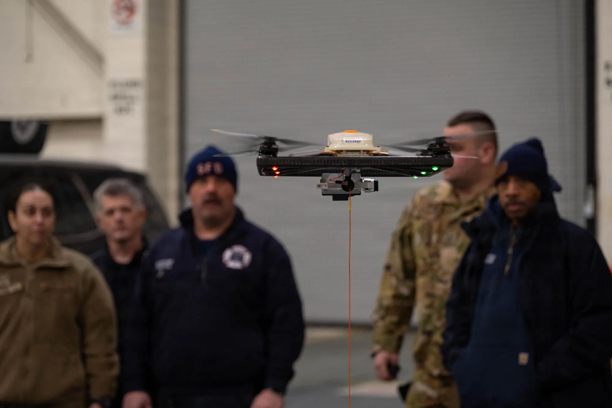
The strongest fit is a mission that benefits from keeping a sensor above one operating area. Tethered-drone training took place at Stewart Air National Guard Base on February 9, 2026; the 105th Airlift Wing's image record identifies situational awareness as the purpose.
Other documented examples on Elistair's Safe-T page include event monitoring and ski-event broadcasting. A mobile-base research application appears in Beffert and Zell's aerodynamics paper, which investigates a drone above an agricultural vehicle. Moving-base capability needs its own assessment because relative motion and cable forces change.
Specify the observation before choosing the height
For a stationary observation task, write down what the operator must distinguish, where those subjects will be, and which obstructions interrupt the required view. Use those requirements to define candidate base locations and sensor configurations. Asking only for maximum height leaves the actual observation task unspecified.
For example, an incident team might need a persistent overview of an access route while another user needs detail from one entrance. Treat those as separate viewing requirements in the demonstration plan. Ask for the required views at the planned stand-off distance, with the intended display and data connection, rather than accepting an unrelated video sample.
Include the cable in the site review. Trace its possible positions between the station and aircraft through deployment, observation, and retrieval. Check the proposed arrangement against vehicles, access routes, overhead obstructions, and the landing area. These are planning questions derived from the cable-geometry and interface constraints above, not a claim that one generic clearance distance fits every system. If the base location cannot support both the required view and the cable path, revise the deployment concept before selecting hardware.
Choose a tethered approach when the required view can be maintained from a workable base location and the complete system can meet the observation duration and recovery requirement. For a route inspection, ask how often the base would have to move and whether the entire cable path remains clear. If these requirements defeat the mission, compare free flight or a ground-mounted sensor before adding tether hardware.
The decisive next step is a complete-system review with three explicit outputs: a power budget, a data-path drawing, and a recovery demonstration plan. Those reveal more about usable capability than cable length or an endurance headline alone.
Sources
- Dicembrini and colleagues, Modelling and Simulation of a Tethered UAS, 2020. Original simulation research connecting changing cable length, aircraft motion, and a winch-model interface.
- Beffert and Zell, Cable Optimization and Drag Estimation for Tether-Powered Multirotor UAVs, v1, April 2025. Original research on electrical delivery and the cable mass/power tradeoff.
- TethPower TP-P2.5 technical description. Manufacturer specifications for rated versus peak power and battery integration; no independent performance verification implied.
- Elistair Safe-T 2 product documentation. Manufacturer information on station monitoring, cable length, and application examples.
- Elistair support FAQ. Data-path options, aircraft-dependent interfaces, and operating-duration limitations; its cable-length description differs from the product page.
- Beffert and Zell, Modeling of UAV Tether Aerodynamics for Real-Time Simulation, v1, December 2025. Original modeling and flight-measurement research on cable shape and forces, with stated model limitations.
- He and Zhang, Stability Parameter Range of a Tethered Unmanned Aerial Vehicle, 2022. Numerical research on wind-driven tension, elongation, and vibration; not a product flight envelope.
- FAA checklist for public-safety actively tethered UAS, August 2024. Official guidance for the U.S. statutory pathway and its conditions.
- 105th Airlift Wing / DVIDS, image 9591668. Official historical photograph and caption documenting tethered-drone training in February 2026.
Last checked: September 6, 2026.