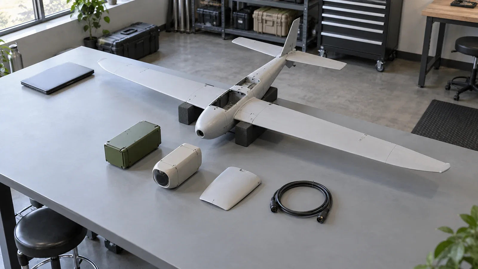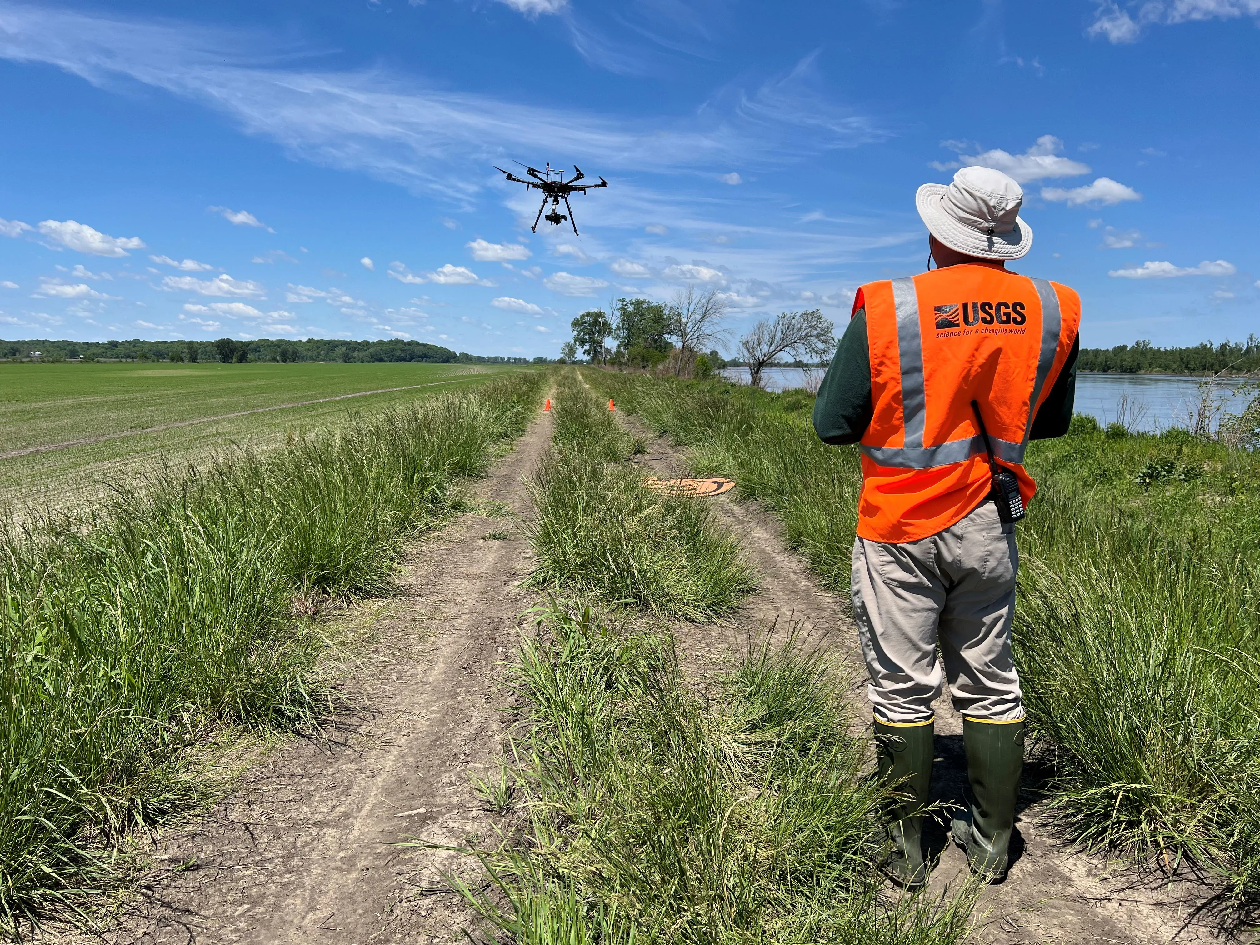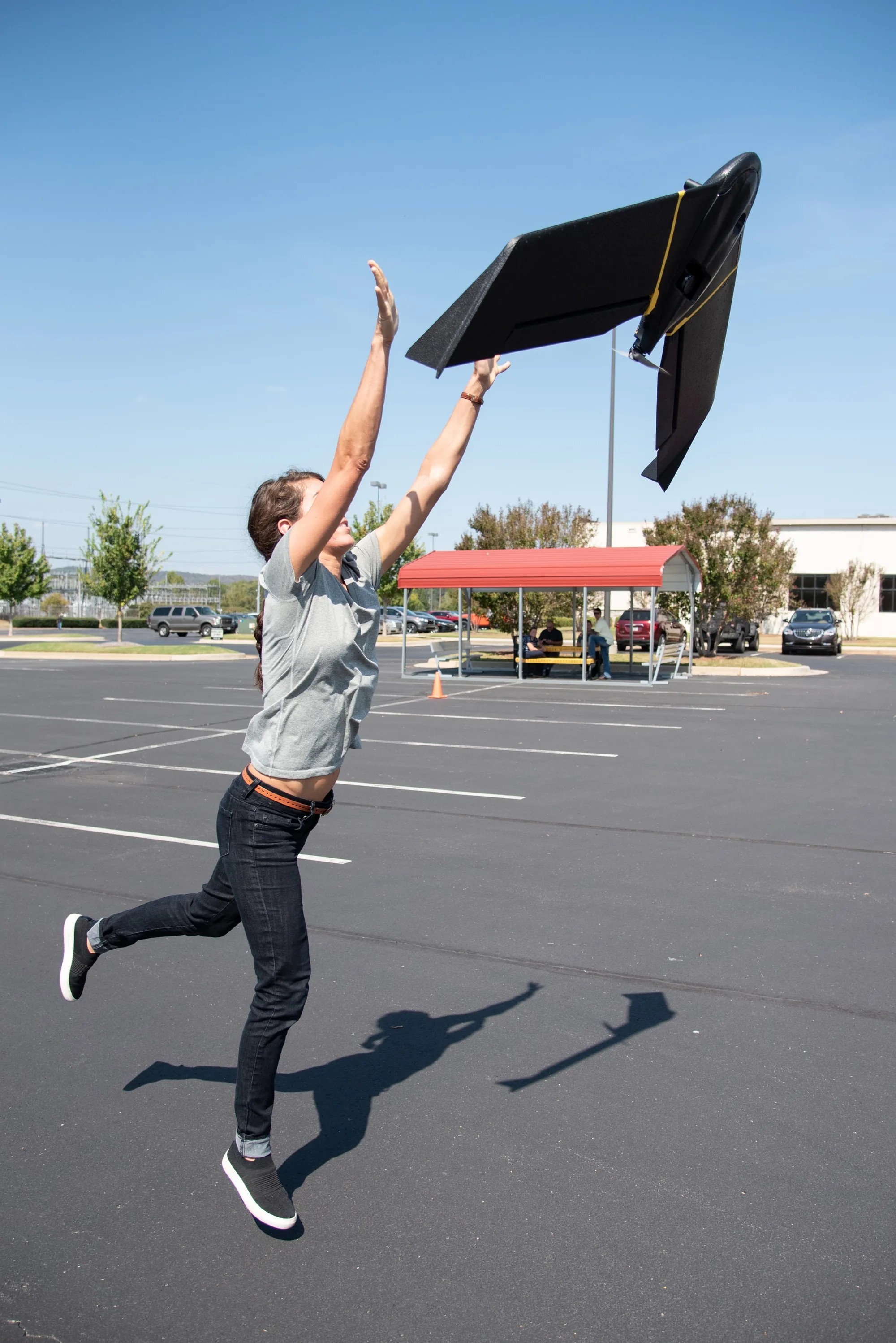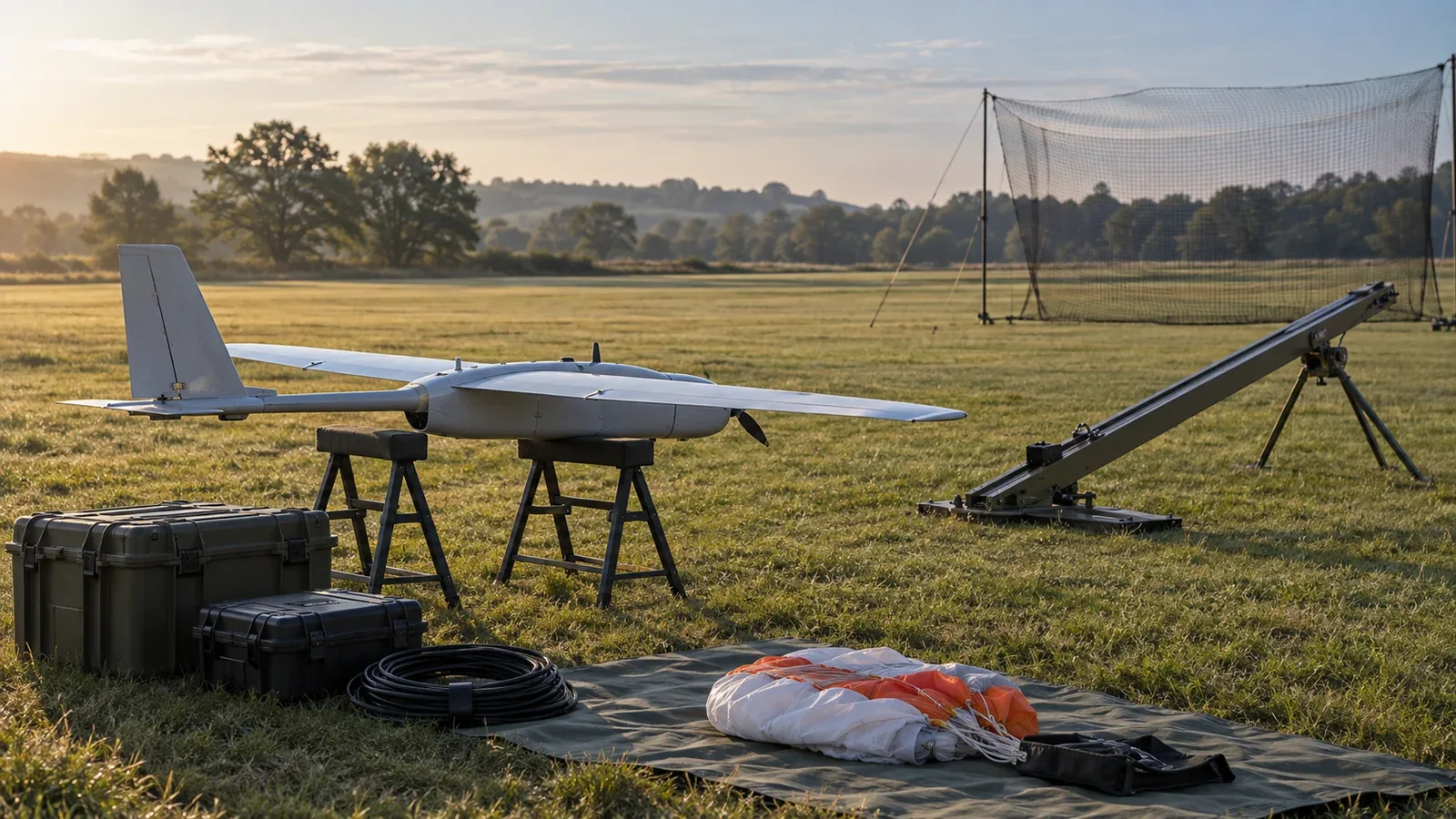
UAS launch and recovery methods move an unmanned aircraft from a supported state into controlled flight and back to a recoverable condition. The main choices are runway operations, hand or mechanical launch paired with a landing or capture system, and vertical takeoff and landing. Each choice moves equipment, energy demand, and operating constraints between the aircraft and its ground system.
Evaluate the launch and recovery pair before choosing the aircraft. A launcher can remove the takeoff runway requirement while leaving a substantial landing-area requirement. A vertical landing can reduce the touchdown footprint while still requiring room for approach, deceleration, and a missed landing.
On This Page
- Compare the complete operating pair
- How the aircraft enters controlled flight
- How recovery removes speed and height
- Define the interfaces before integration
- Plan for failures at each handover
- Match the method to the operating site
- Specify the recovery demonstration
Compare the complete operating pair
Treat the following as an engineering comparison of mechanisms, not a ranking of aircraft. Site suitability depends on the exact airframe, equipment, payload, weather envelope, and crew procedures.
| Operating pair | Where the work happens | Main integration question |
|---|---|---|
| Runway takeoff and wheeled landing | Aircraft propulsion, flight controls, landing gear and prepared surface | Can the available surface and approach accommodate the actual configuration? |
| Hand or rail launch and belly landing | Person or launcher starts flight; airframe contacts the recovery surface | Is the landing surface compatible with the fuselage, propeller and payload? |
| Mechanical launch and net or line capture | Ground equipment supplies launch energy and arrests the returning aircraft | Are capture geometry, attachment loads and the missed-capture route demonstrated together? |
| Launch followed by parachute recovery | The canopy slows descent; the airframe still absorbs touchdown | Are deployment conditions, landing dispersion and retrieval access acceptable? |
| Rotorcraft vertical takeoff and landing | Aircraft carries the lift system throughout the flight | Can it support the required landing power and maintain control at the site? |
| Hybrid VTOL takeoff, wingborne cruise and vertical landing | Aircraft changes between rotor-supported and wing-supported flight | Is there sufficient transition space and a defined response if the transition cannot finish? |
Source basis: the ArduPilot takeoff/landing documentation, Insitu and FLY-R equipment descriptions, Aeromao's recovery examples, and PX4 transition documentation listed below. The questions are engineering interpretation; these combinations do not establish compatibility between independently selected components.
How the aircraft enters controlled flight
Runway, hand and mechanical launch
A runway aircraft accelerates along the surface before its wing carries it into flight. A hand or mechanical launch supplies the initial motion without that ground roll. After release, the aircraft must establish controlled flight with its own propulsion and aerodynamic controls.
The release event and motor-start logic need to agree. ArduPilot's automatic-takeoff documentation describes acceleration, delay and speed conditions used in hand and catapult launch. It specifically identifies propeller clearance from the hand or launcher as a concern. A launch command is therefore not equivalent to a verified, unobstructed release.
For a mechanical launcher, ask the supplier to define the accepted aircraft mass and attachment arrangement, release confirmation, and handling of an interrupted launch sequence. These are interface questions, not interchangeable settings. FLY-R's launcher description provides a vacuum-powered example; Insitu's ScanEagle page describes a rail-launch configuration paired with Skyhook recovery.
Vertical launch and transition
Rotorcraft produce lift without first accelerating along a runway. Hybrid VTOL aircraft subsequently transfer to wingborne flight. The integration burden includes the transfer of control between flight regimes and the reverse transition during recovery.
PX4's back-transition guide explains why the reverse transfer needs deceleration space: the aircraft must slow before multicopter control takes over. Transition timing and expected deceleration influence where that happens, and the documentation notes possible drift during the transition. A marked landing pad alone does not describe this flight volume. Compare the approach and transition corridor as well as the touchdown area.
There is also an architectural distinction between onboard VTOL machinery and a separate lifting device. Insitu describes FLARES as an alternative launch/recovery kit for ScanEagle. The label “VTOL” should prompt a question about which vehicle carries the lifting hardware and what equipment must accompany the mission.
How recovery removes speed and height
Runway or belly landing
A conventional fixed-wing recovery uses an approach, controlled descent and flare before contact. With wheels, the aircraft rolls on landing gear; a belly landing uses an airframe designed to contact the surface directly. The distinction matters when examining protruding sensors and the permitted recovery surface.
ArduPilot's automatic-landing guide connects landing performance to an attainable glide path, approach alignment and flare timing. It also highlights home-altitude reference and barometer drift. An accurate horizontal destination does not establish accurate height above the touchdown surface.
Net and line capture
Capture equipment brings the aircraft to rest through a purpose-designed contact or attachment. A net presents a capture area; a line system uses a compatible aircraft capture mechanism. Review the load path through the aircraft and ground equipment, not just the navigation accuracy at the interception point.
FLY-R describes a net-recovery system and separates ground testing from moving-ship validation in its equipment account. That distinction is useful: a fixed-site demonstration should not be treated as proof of moving-deck performance. Insitu's rail/Skyhook combination is another documented runway-independent architecture, without implying that arbitrary aircraft can use its equipment.
Parachute recovery
A parachute increases aerodynamic drag to slow descent. NASA's falling-object explanation shows the underlying balance: terminal speed occurs when drag balances weight. Slower descent still ends in contact with the surface; canopy deployment is not itself a completed recovery.
Aeromao identifies parachute recovery for the Aeromapper Talon in its official product lineup. It separately describes the Talon Amphibious as belly landing on water and using a parachute on land. Those are model-specific examples, not permission to water-land another fixed-wing aircraft.
For a proposed parachute system, request evidence for deployment conditions, touchdown loads, wind-related landing dispersion, repacking and retrieval. Also distinguish a parachute intended for routine recovery from an emergency system intended to mitigate a failure. One purpose does not establish suitability for the other. Request the airframe-specific deployment and inspection instructions; a generic canopy description cannot establish them.
Define the interfaces before integration
A useful system boundary includes the aircraft, launcher or landing equipment, navigation sensors, flight controller, ground-control station and crew. Document who authorizes each transition: ready to launch, released, established in flight, committed to recovery, in contact, and safe to handle. Use observable conditions rather than relying on a single “mission complete” indication.
Precision landing adds a target-sensing chain. MAVLink's Landing Target Protocol carries target information from a positioning system to an autopilot. Its documentation distinguishes image-relative angles from position fields and identifies different supported coordinate frames for PX4 and ArduPilot. Supporting the same message name does not establish matching interpretation.
Specify units, coordinate frame, sensor orientation, observation time, update rate and invalid-data behavior. Verify the chosen flight-stack release and the companion computer together. The publication's sensor-fusion guide explains why timing, calibration and reference frames need to agree before measurements can support control.
The energy interface needs a separate check. Ask whether the vehicle has both enough remaining energy to finish recovery and enough available power for the landing maneuver. A hybrid's cruise condition is not a substitute for its vertical-landing condition. Battery management systems for unmanned vehicles explains the difference between charge estimation, pack limits and vehicle decisions.
Plan for failures at each handover
The important question is what the system will do when a necessary condition disappears. “Return home,” “automatic landing,” and “precision landing” do not describe identical behavior.
PX4's precision-landing documentation distinguishes required and opportunistic modes. In required mode, an unsuccessful target search can end in a normal landing at the current position. Target loss during final approach can also allow descent to continue. The mode name alone does not guarantee landing on the target. Confirm behavior against the installed release, including what happens after a search timeout. For a pad surrounded by obstacles, fallback to the current position may be unacceptable.
Use this failure review to define demonstration cases. It is an engineering checklist derived from the cited control and equipment documentation, not a claim that any particular aircraft implements the response requested.
| Boundary being crossed | Failure to examine | Evidence to request |
|---|---|---|
| Restraint to free flight | Release fails or motor timing conflicts with clearance | Interlock states and the approved interrupted-launch procedure |
| Approach to touchdown | Incorrect height reference or unstable approach | Defined abort criteria and a demonstrated missed approach |
| Wingborne flight to hover | Deceleration or transition does not complete as expected | Position, speed and mode logs with the documented fallback |
| Target acquisition to descent | Missing, stale or misinterpreted target information | Target-loss behavior in each landing phase |
| Flight to capture | Aircraft misses the net or capture line | Clear escape route and criteria for another attempt |
| Parachute deployment to retrieval | Unexpected descent or inaccessible landing position | Deployment envelope, dispersion evidence and retrieval plan |
Check when a retry remains possible and when the system is committed to contact or descent. Establish who can interrupt the sequence and how that authority is indicated to the crew. Avoid a procedure that assumes the next attempt will always be available.
Match the method to the operating site
For a survey team using open terrain, compare the complete recovery area and retrieval work for belly or parachute landing with the support needed for vertical landing. A compact launch kit is useful only if the returning aircraft can also be recovered without unacceptable payload damage or site access demands.
For a ship or moving platform, evaluate relative motion, approach clearance, deck operations and securing the aircraft after recovery. A manufacturer's fixed-site capture result or a controller's target-tracking feature is a starting point for questions, not a complete demonstration of the proposed shipboard installation.
For a repeatable fixed base, runway access may be compatible with the mission, while a rotorcraft pad may better suit another site's geometry. Compare daily servicing, launch/recovery crew tasks and recovery interruptions alongside flight endurance. These are scenario-based selection criteria rather than product recommendations.
Specify the recovery demonstration
Before committing to a launch/recovery architecture, request one demonstration plan covering the actual aircraft configuration, payload, site geometry, environmental limits, recovery equipment and control software. Include nominal operation, a missed approach or capture, sensor loss, and the applicable interrupted-transition behavior. Agree how hazardous cases will be demonstrated through simulation or controlled trials, rather than introducing unplanned failures during routine operations.
Define success through safe recovery and readiness for inspection, not simply arrival at a coordinate. Ask what inspection follows landing or capture, which components have replacement limits, and how configuration changes affect the demonstrated envelope. The broader UAS airworthiness guide puts those maintenance and configuration questions in context.
Select the pair that can demonstrate the required mission repeatedly with an acceptable site footprint, support burden and failure response. The decisive evidence is the complete recovery sequence under the proposed conditions.
Sources
- ArduPilot: Automatic Takeoff. Flight-controller documentation for ground, hand and catapult takeoff logic.
- ArduPilot: Automatic Landing. Approach, flare, altitude-reference and abort considerations.
- Insitu: ScanEagle. Manufacturer description of rail/Skyhook and FLARES architectures.
- FLY-R: Launcher and Recovery. Manufacturer account of vacuum launch and net recovery; test-stage statements are limited to the page's account.
- Aeromao: Products. Manufacturer identification of parachute and amphibious recovery examples.
- NASA Glenn: Falling Object with Air Resistance. Physical explanation of drag, weight and terminal speed.
- PX4: VTOL Back-transition Tuning. Main-branch documentation of deceleration, timing and drift.
- PX4: Precision Landing. Main-branch documentation of target acquisition and fallback behavior.
- MAVLink: Landing Target Protocol. Target-message fields and implementation-specific frame support.
Last checked: September 10, 2026.