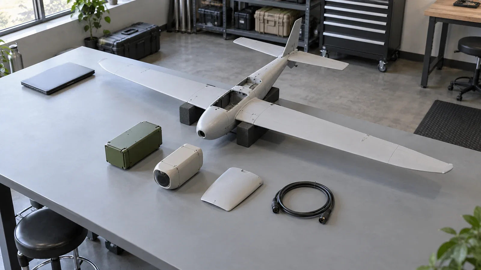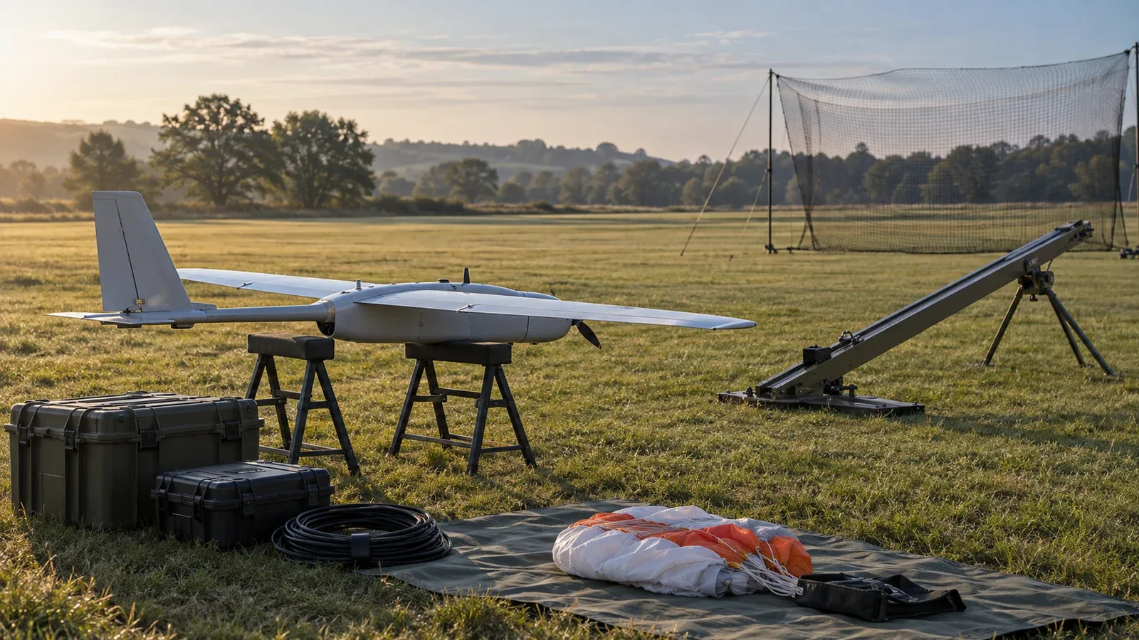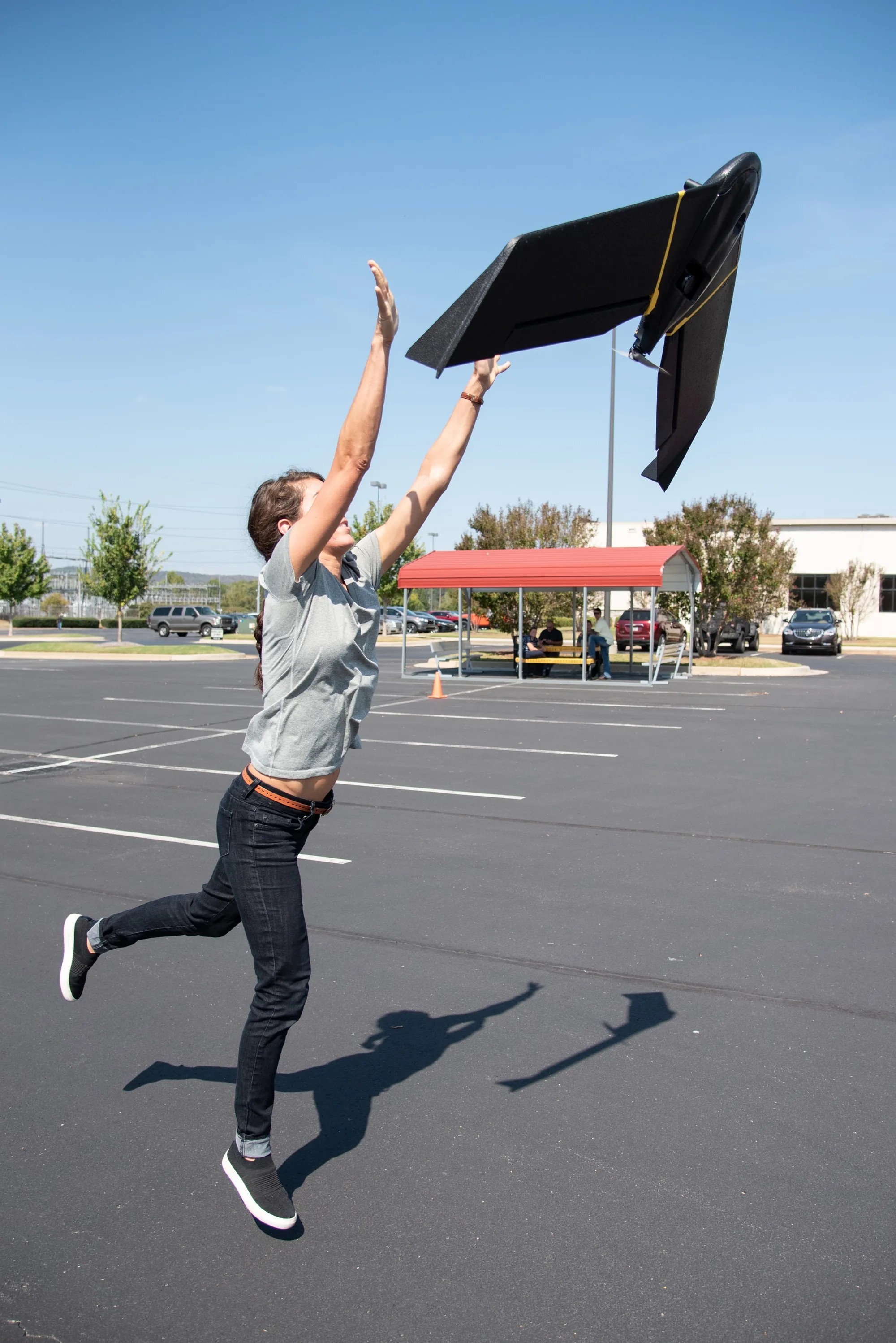
An unmanned aircraft system combines an aircraft with the equipment needed to operate it: flight controls, navigation sensors, communications, ground controls, and supporting power systems. A mission payload adds the camera, instrument, or cargo that gives the flight its purpose. The components work together through two connected paths: controlling flight and producing the mission's result.
The FAA's UAS definition places the aircraft inside that larger operating system. For engineers and program managers, the practical question is where each function runs, what it depends on, and what happens when an input disappears. The software examples below use PX4 v1.16 documentation; another system's behavior must be established separately.
On This Page
- The components and their boundaries
- How a movement command becomes flight
- What crosses the interfaces
- Power and performance tradeoffs
- Failures follow dependencies
- How the mission changes the architecture
- Review the complete system
The components and their boundaries
A useful UAS description separates functions even when a manufacturer combines them inside one enclosure. The following map uses a small electric aircraft as its reference. Larger aircraft, fuel-powered systems, and specialized launch or recovery arrangements change the hardware without eliminating the need to identify these functions.
| Component | Main job | Connection to examine |
|---|---|---|
| Airframe and propulsion | Support the installed equipment and produce controlled flight | Motor or servo arrangement, physical mounting, and actuator commands |
| Energy supply and distribution | Feed propulsion, avionics, and payloads at suitable voltages | Regulators, wiring, current measurement, and shared supply paths |
| Navigation sensors | Measure motion, pressure, position, or other useful quantities | Sensor orientation, timestamps, electrical connection, and data validity |
| Flight controller and flight software | Estimate aircraft state and calculate control outputs | Sensor inputs, requested motion, flight mode, and actuator outputs |
| Communications equipment | Carry control requests and aircraft status between systems | Radios, antennas, serial or network links, and loss detection |
| Ground control station | Let an operator plan, command, and monitor the operation | Displayed aircraft state, operator input, and payload controls |
| Mission payload | Capture observations or carry and release an item | Mount, power, triggering, storage, and status feedback |
| Optional companion computer | Run additional processing or external flight-control logic | Connection to the flight controller and responsibility during failure |
Source basis: the PX4 v1.16 system architecture, component overview, and power-system documentation. The connection questions are engineering synthesis, not a prescribed equipment standard.
The flight controller is the computing hardware; the flight stack is the software running on it. A companion computer is optional. PX4 illustrates both a controller-only system and one that adds a computer for functions such as computer vision. A more powerful processor does not by itself establish which flight functions it performs or whether the aircraft can continue without it.
How a movement command becomes flight
Consider a multirotor following a position target. The operator or mission logic supplies the desired position. Sensors describe the aircraft's motion, and an estimator combines those inputs into an estimate of its current state. Controllers compare the target with that estimate and calculate the attitude and thrust needed to reduce the difference. The system then translates the requested forces and moments into individual actuator commands.
An electronic speed controller, or ESC, drives an electric motor in response to its command. Servos move control surfaces on aircraft that use them. The resulting motion changes the next sensor readings, closing the feedback loop. This explanation follows the PX4 v1.16 flight-stack architecture; the exact control arrangement depends on the vehicle and mode.
Navigation is an estimate, not one sensor reading
An inertial measurement unit, or IMU, supplies gyroscope and accelerometer measurements. A satellite-navigation receiver supplies another kind of information. Barometric pressure, magnetic heading, range, or vision measurements may also contribute, depending on the installed system.
Those inputs arrive with different delays. PX4's v1.16 navigation-filter documentation describes buffering sensor data so the estimator can combine measurements at the appropriate time. It also accounts for the IMU's physical offset when providing position and velocity to the control loops.
This makes timing and mounting part of navigation performance. A sensor can send plausible numbers while its orientation, delay, or reference is wrong for the estimator. Integration therefore needs to establish what each measurement means and when it was taken, as well as whether the device is connected.
Mission execution and external control have different dependencies
A mission held onboard and a controller streaming movement targets from another computer create different failure paths. In PX4 v1.16 Offboard mode, external control requires a continuing signal that the source is alive. If that signal stops, the flight stack leaves Offboard mode after the configured timeout and applies its configured response.
The external source may be a companion computer aboard the aircraft. “Offboard” here means outside the flight stack, not necessarily on the ground. Specify whether losing that computer removes only image processing, removes navigation input, or removes the active source of flight commands.
What crosses the interfaces
Command and control, often shortened to C2, carries the information used to direct the aircraft. Telemetry reports its state. Payload controls and mission data, such as images, serve additional purposes. A single radio or network may carry multiple flows, so identify which services remain available when one flow fails.
PX4's system architecture example includes sensor buses such as I2C, SPI, CAN, and UART, plus serial or IP communication with a companion computer. These names identify connection technologies. They do not establish that two devices understand the same messages or use compatible electrical interfaces.
For each boundary, document the connector and electrical requirements, protocol version, supported messages, units, coordinate frame, update timing, and behavior when data become stale. These questions turn a general compatibility claim into something an integration team can verify.
Acknowledgement is different from physical completion
The MAVLink command protocol provides acknowledgements and retry behavior. A command can be accepted, rejected, or reported as in progress. An initial acceptance means the flight stack will attempt the command; it does not prove the requested physical action has finished.
For a payload-release request, for example, ask what confirms the mechanism actually moved. For a positioning request, inspect the reported vehicle state. The command response and the mission result answer different questions.
More telemetry is not automatically better telemetry
MAVLink's streaming guide explains that default message sets are limited to reduce channel traffic and that supported requests can change message intervals. Choose update rates around the information the receiving function needs. Then check the delivered rate and age of the data when the link is carrying its intended traffic.
A live connection can still present old information. As an illustrative calculation, an aircraft travelling at 10 metres per second moves 2 metres during a 0.2-second delay: distance = speed × time. This is not a predicted positioning error. It shows why message age matters alongside link availability.
Power and performance tradeoffs
An electric UAS needs a power architecture as well as a communications architecture. PX4's power-system guide distinguishes regulated flight-controller power from supplies for motors, servos, and peripherals. A power module may also measure battery voltage and current.
When adding a payload, ask both whether the aircraft can carry it and whether the supply can support it. Trace common regulators and wiring: two functioning computers are not independent of a supply path they share. Peak demand and the response to a peripheral fault belong in the integration review.
Remaining energy is also an estimate. PX4's battery-estimation documentation explains that terminal voltage changes under load and describes combining voltage-based estimation with measured current consumption. A displayed percentage is therefore not a universal promise of remaining flight time. Compare configurations under the intended load and flight profile, with the chosen reserve and recovery requirement stated.
The airframe changes what the energy buys. PX4's vehicle overview describes multirotors as suited to hovering and vertical takeoff, while conventional fixed-wing aircraft generally offer longer, faster flight and broader survey coverage. Hybrid vertical-takeoff-and-landing aircraft combine vertical operation with wing-borne flight, adding transition and tuning complexity.
These are broad configuration tradeoffs, not matched performance measurements. A hover requirement can rule out a conventional fixed-wing aircraft even when its cruise endurance is attractive. Conversely, a large-area mission may place more value on efficient forward flight than on remaining stationary over one point.
Failures follow dependencies
Ask which function is lost before choosing a response. The following distinctions are based on PX4 v1.16 failsafe documentation and its Offboard-mode requirements. They are architecture questions, not aircraft-specific emergency procedures.
| Failure | What changes | What must be established |
|---|---|---|
| Ground-station telemetry disappears | The ground connection is lost | Detection timeout, mode exceptions, and configured aircraft action |
| Manual-control input disappears | Pilot input is unavailable | Whether the current mode needs that input and which response applies |
| Position estimate becomes unacceptable | Position-dependent control loses a required input | Remaining navigation capability and the response for that mode |
| External control stream stops | The flight stack loses its continuing external-control signal | Timeout, fallback mode, and availability of manual control |
Position loss can remove a dependency that a return-to-home response needs. Establish behavior for combined failures, including the information available to the operator.
A failed payload can also leave the aircraft controllable while making the mission unsuccessful. In the component map above, follow its power and data connections to determine whether the fault stays within the payload or can affect flight functions. That is a question about the actual installation, not something the payload label answers.
Redundancy also needs a defined scope. PX4's estimator guide distinguishes sensor selection before a single estimator from running multiple estimator instances. Protection against a missing data stream is not necessarily protection against plausible but incorrect measurements. Specify which faults the complete arrangement can detect and tolerate.
How the mission changes the architecture
Mapping requires a measurement chain
Mapping adds requirements beyond completing a route: imagery must support the intended geographic measurement. USGS calibration guidance identifies data acquisition, geometric and radiometric calibration, and quality control as parts of producing quantitative UAS data. It also explains that ground-control and tie-point quality affect geometric accuracy independently of ground sample distance.
The resulting design question is how capture, positioning, calibration, and processing connect. A camera resolution or navigation specification alone does not establish the accuracy of the delivered map.
Environmental sensing changes the payload and interpretation
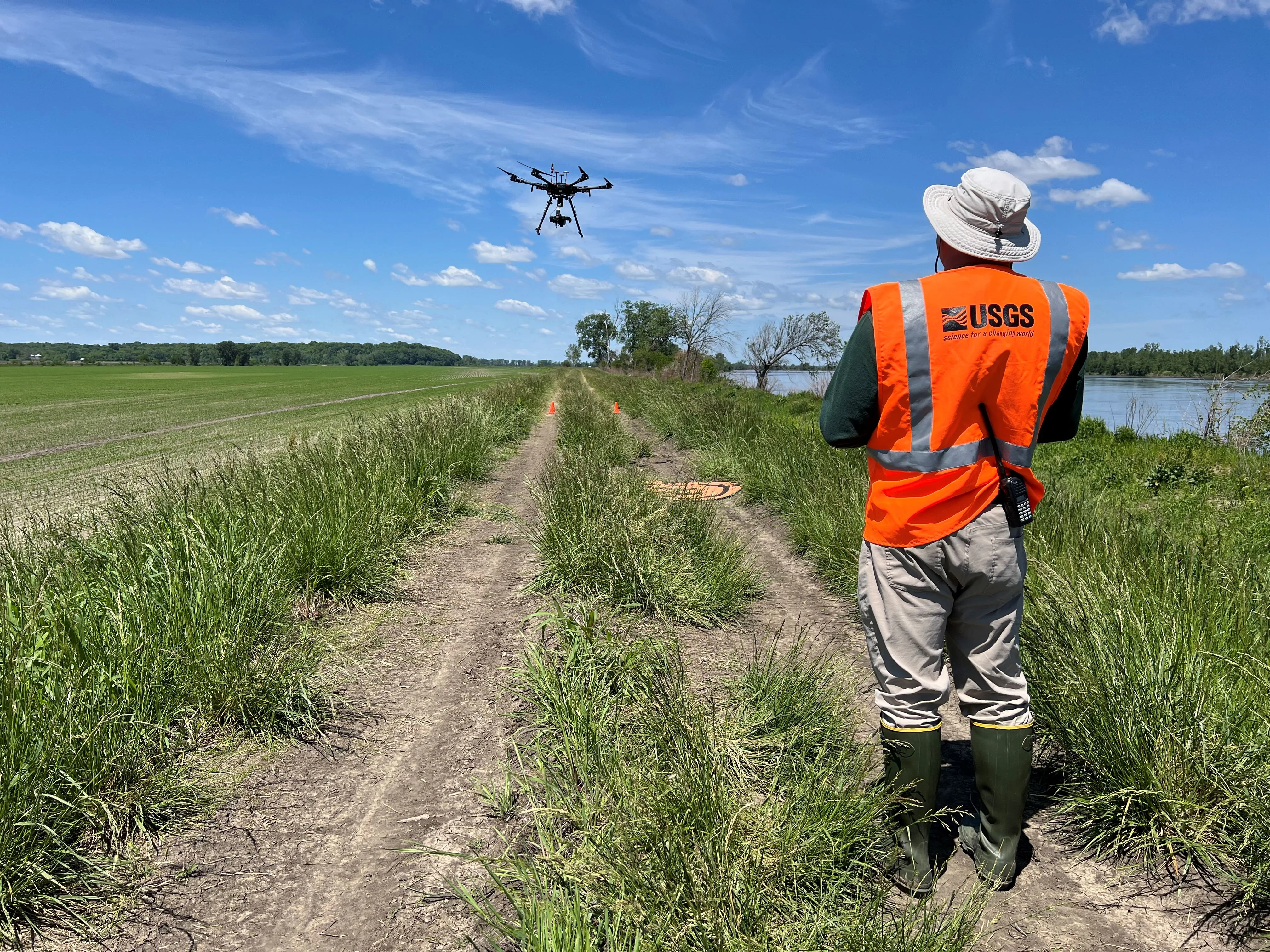
In a May 2024 Missouri River study, USGS used an aircraft carrying a hyperspectral payload to support work on river-flow patterns and habitat. The featured photograph documents that operation.
Here, carrying the appropriate sensor is only one part of the mission. The scientific question determines what observations are needed and how they will be interpreted. An aircraft suitable for ordinary photography cannot be assumed to deliver the same measurements merely because it can follow the same route.
Delivery adds a physical completion condition
PX4's v1.16 delivery-mission guide describes using a gripper and proceeding after the release operation indicates completion. That indication can come from sensor feedback or a configured timeout. The guide also describes a case where a conflicting manual gripper command prevents release but the mission resumes after its command timeout.
In a delivery design, distinguish arrival, a release command, and evidence that the item was released. Ask exactly what the completion indication measures. Elapsed time and a sensor observing the mechanism provide different information.
These examples lead to different system requirements even when they share an airframe. Start with the required observation or action, then trace the equipment and interfaces needed to produce it.
Review the complete system
Before accepting a UAS architecture, ask the supplier or integration team to walk through one normal mission and one interrupted mission:
- Where do flight targets originate, and which controller acts on them?
- Which measurements support the active flight mode?
- What data and power paths are shared between essential functions?
- What tells the operator that a command was accepted and that its result occurred?
- What continues, changes mode, or stops when each required input is lost?
- What verifies the delivered observation or physical action?
The answers should refer to the actual hardware, software version, configuration, and mission. A component list describes what is installed. Following these paths explains how the aircraft stays controlled and how the operation produces its intended result.
Sources
- FAA: What is an unmanned aircraft system? Agency definition establishing the aircraft and operating-equipment boundary.
- PX4 v1.16: Basic Concepts Project manual covering components, payloads, ground controls, and broad airframe tradeoffs.
- PX4 v1.16: System Architecture Documented controller-only and companion-computer arrangements and connections.
- PX4 v1.16: Architectural Overview Flight-software explanation of estimation, control, and actuator outputs.
- PX4 v1.16: Navigation Filter Estimator inputs, timing, reference offsets, and sensor-fault limitations.
- PX4 v1.16: Offboard Mode External-control inputs, continuing signal requirements, and loss response.
- MAVLink: Command Protocol Protocol documentation distinguishing acknowledgements, progress, and completion.
- MAVLink: Request and Stream Messages Protocol guide explaining message intervals and channel traffic.
- PX4 v1.16: Power Systems Supply distribution and power measurement.
- PX4 v1.16: Battery Estimation Load effects and voltage/current-based remaining-capacity estimation.
- PX4 v1.16: Failsafe Configuration Separate control-link, telemetry-link, and position-loss responses.
- PX4 v1.16: Package Delivery Missions Gripper operations and the distinction between release feedback and timeout-based completion.
- USGS: Guidelines for Calibration of Uncrewed Aircraft Systems Imagery Open-File Report 2023-1033 on acquisition, calibration, and geometric data quality.
- USGS: Hyperspectral UAS operation on the Missouri River Official May 2024 mission photograph and description; image marked public domain.
Last checked: September 6, 2026.