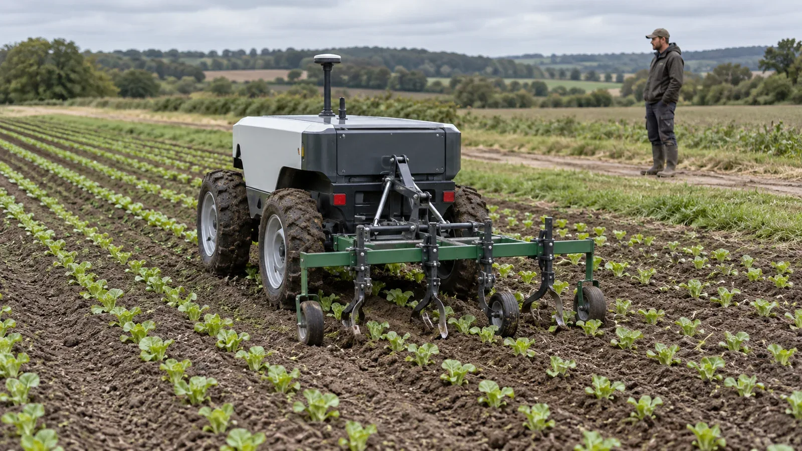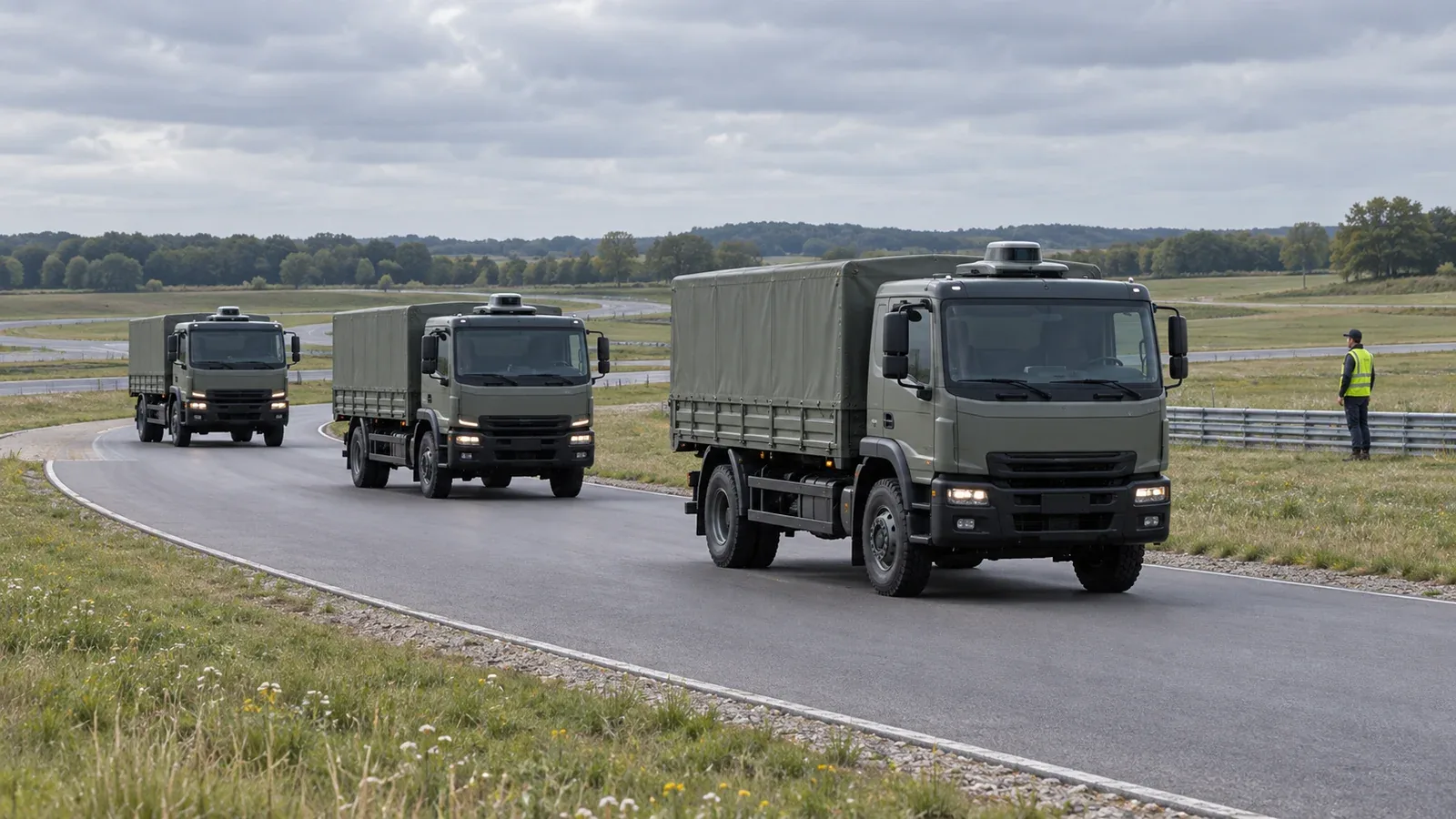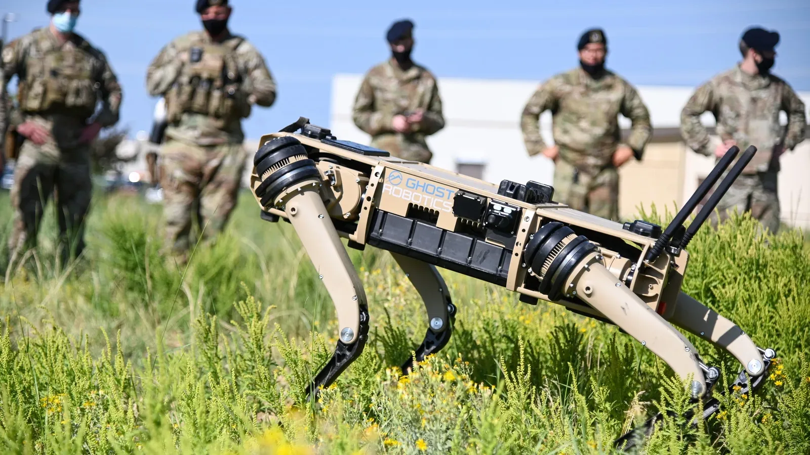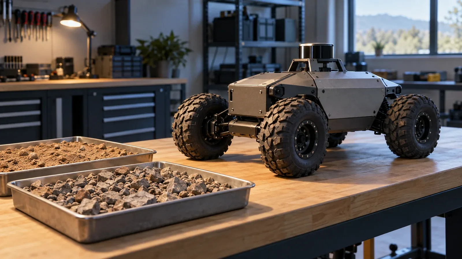
Off-road mobility is an unmanned ground vehicle's ability to turn commanded motion into controlled progress across uneven or deformable terrain. It depends on ground contact, vehicle geometry, available power and the control system's understanding of the surface. A route can be free of visible obstacles and still be undrivable because the soil cannot support the vehicle or its wheels cannot develop useful traction.
For a UGV, mobility therefore spans the chassis and the autonomy system. Engineers need to ask whether the vehicle can cross, steer, stop and recover with its actual payload, rather than treating a maximum climbing angle as a complete description of capability.
On This Page
- From terrain observations to wheel motion
- Why clear ground can still stop a vehicle
- Interfaces that make mobility work
- Trade speed against control and endurance
- Recognize the failure before choosing a response
- How applications change the design
- Test the mission configuration
From terrain observations to wheel motion
A useful architecture separates four jobs: estimating vehicle motion, describing the terrain, selecting a feasible trajectory and executing that trajectory. The outputs feed back into the next decision as the vehicle moves.
CMU's Autonomous Off-Road Driving project illustrates this arrangement. It combines camera, lidar, inertial and GPS observations for pose estimation; reconstructs and classifies nearby terrain; uses aerial imagery and elevation data for global planning; and simulates vehicle travel over a local terrain model to select a path.
The practical distinction is between a map of occupied space and a prediction of what this vehicle can traverse. A rock's height matters, but so do its position under the vehicle and the approach trajectory. The sensor-fusion explanation develops the timing, calibration and uncertainty issues behind the pose estimate that holds these observations together.
At the output end, a trajectory must become achievable steering and drive commands. Treat wheel speed as one observation of motion, not proof that the chassis advanced: slipping wheels can turn while the vehicle makes little progress.
Why clear ground can still stop a vehicle
Terramechanics describes the interaction between a vehicle and the ground. On soft soil, the contact surface must support the load while transmitting forces that move and steer the vehicle. Excessive slip can disturb the soil and increase sinkage, leaving the vehicle digging instead of advancing.
Zhang and colleagues' 2022 wheeled-bevameter research explains why visual classification alone is insufficient. Similar-looking surfaces can behave differently as their material properties change. Their experimental system probes the ground with an instrumented wheel to estimate slip and sinkage before the rover commits its supporting wheels. This is a research approach, not a capability shared by all UGVs.
For integration, separate three questions: will the ground support the load, can the contacts produce useful motion, and can the body clear the terrain? An answer to one does not establish the others. Keep geometric clearance and estimated soil support separate in the planner, with uncertainty attached to each.
Vehicle articulation adds another variable. JPL's RoboSimian research platform uses driven wheels on articulated limbs to change its shape and center-of-mass position relative to ground contacts. Such mechanisms create additional ways to negotiate terrain, but their joint states and movement limits also become part of planning. A route model built for a fixed chassis cannot simply assume those motions are available.
Interfaces that make mobility work
The following interface questions are an engineering synthesis of the documented perception architectures and vehicle manuals. They are useful review items, not a universal communications standard.
Between perception and planning, specify the coordinate frame, observation time, estimated ground surface and uncertainty. Distinguish an unobserved patch from ground classified as traversable. Between planning and drive control, specify whether commands represent chassis speed and curvature, steering angle or individual wheel targets. Agree on units, limits and how commands expire.
The return path needs achieved motion and health information. A controller should know when its requested output has been limited; the planner should not continue predicting a trajectory as though full drive authority remains available. Record which component can reduce speed, reject a command or request a stop, and define what happens when telemetry or commands become stale.
Clearpath's Husky A200 manual gives a concrete reason to inspect telemetry definitions. Its reported total current excludes the motor drivers, and motor-case temperature lags the temperature of the coils inside. A field log that labels either value simply as “vehicle load” can conceal the condition an engineer needs to diagnose.
Keep battery limits in the same conversation. The battery-management guide explains why charge estimates and available power are different signals. Route execution needs the relevant current and protection limits, not only a remaining-charge percentage.
Trade speed against control and endurance
Steering is part of the energy budget. Clearpath warns that rough travel and turning in place can produce large current spikes on the A200, and suggests wider-radius turns to reduce demand. A route planner that optimizes distance alone may repeatedly select maneuvers that are harder on the drivetrain. This does not mean every wider path saves energy; compare the complete route and operating conditions.
Terrain-aware planning can also learn from physical interaction. Sivaprakasam and colleagues describe using a learned model to assign costs based on how well a vehicle is expected to follow a candidate path. That provides a way to include behavior that a simple obstacle map misses. The result still needs evaluation on the intended vehicle and terrain; experience in one environment does not establish performance everywhere.
Speed makes the information path consequential too. CMU's TartanDriver account describes combining lidar, cameras, inertial measurements, shock travel and wheel encoders with uncertainty-aware autonomy. More sensing is useful only if the information reaches the motion decision in time. The edge-AI explanation examines the sensor-to-command latency behind that integration choice.
A practical review should compare the age of the terrain estimate with the vehicle's movement since that observation. Faster inference alone cannot compensate for an old image, delayed pose estimate or controller that receives commands late.
Recognize the failure before choosing a response
Similar symptoms can have different causes. The table connects the mechanisms above to observations worth collecting. It is an engineering diagnostic aid based on the cited soil research, Clearpath manuals and CMU architecture descriptions; the observations are not conclusive diagnoses.
| Field symptom | Possible mechanism | What to examine before the next attempt |
|---|---|---|
| Wheels turn but progress falls | Slip and increasing sinkage | Independent motion estimate, wheel motion and visible rut development |
| Motion worsens during repeated tight turns | High steering demand or thermal limiting | Turn commands, motor currents and temperature trends |
| Vehicle follows the wrong line despite a plausible map | Pose, timing or command-model mismatch | Sensor timestamps, coordinate frames and commanded versus achieved motion |
| A clear-looking patch proves difficult | Terrain geometry was mistaken for bearing capacity | Ground condition and the basis of the traversability estimate |
| Vehicle moves downhill after a stop command | Stop function does not provide adequate holding behavior | The exact stop mode, slope, payload and manufacturer's holding provisions |
The final row is especially easy to overlook. The Husky A300 manual explicitly warns that the platform can roll on a slope in its emergency-stop state. Stopping drive commands, interrupting motor power and holding position are different functions. Establish what the installed system actually does before placing it on a route where rollback creates a hazard.
Recovery belongs in route planning. Agree in advance how operators will secure and retrieve an immobilized vehicle using its documented procedures. Before attempting further motion, distinguish slip, physical obstruction and a protection limit; each calls for a different response under the vehicle's recovery procedure.
How applications change the design
For emergency-response robots, mobility may center on gaps, steps, loose debris and confined turns while an operator supervises from a distance. NIST's response-robot program provides repeatable methods for measuring individual capabilities across ramps, stepfields, gravel, sand and other challenges. These allow a team to describe the difficult parts of its mission more precisely than “all terrain.”
For longer outdoor routes, the integration emphasis shifts toward sustained perception, changing terrain and the cost of intervention. CMU identifies mining, search and rescue, exploration and wildfire management as motivations for off-road autonomy research. These are application areas, not evidence that one research vehicle is qualified for each working environment.
For planetary exploration research, opportunities to reshape the vehicle or investigate uncertain soil can justify specialized mechanisms. RoboSimian's planetary analogue traverses illustrate that design direction. Its terrestrial research results should not be read as a claim of operational use on another planet.
Payload changes can alter the answer within any application. The A300 documentation ties operation to payload mass and location, describes thermal throttling, and explains constraints on regenerative current during downhill stopping. Treat the battery configuration and payload arrangement as part of the mobility configuration being evaluated.
Test the mission configuration
Start with a route description and the fitted vehicle, then define what counts as successful completion. Record payload placement, tires or tracks, relevant settings, battery configuration, ground condition, control mode and operator involvement. Within the manufacturer's operating limits and the site test plan, repeat difficult maneuvers after sustained operation, when conditions may differ from a cold start.
Ask for a trial record that connects each failure to its location and operating state: where progress stopped, whether the vehicle lost traction or became limited, what intervention occurred and whether recovery was possible. Keep a successful operator-assisted traverse separate from an autonomous completion. These are proposed comparison practices derived from the system interactions above, not claims about a tested product.
NIST makes an essential distinction: its standardized methods measure capabilities, while users set mission-specific performance thresholds. A result on a reproducible obstacle is useful evidence; it does not certify every possible field route.
Make the route comparison reviewable
Build a comparison sheet with one row for each required maneuver, rather than one overall pass box. Identify the approach, surface condition, load arrangement, control mode and completion criterion before the run. Add the observed result, any intervention and the supporting trace or video afterward. Leave an unknown condition marked unknown; a photograph of apparently clear ground should not be entered as a measurement of soil strength. This is a proposed way to connect the article's separate geometry, soil-support and control questions.
Keep baseline runs separate from runs in which conditions deliberately change. Note whether a segment is undisturbed or has already been crossed, and identify any changes to the route or vehicle between attempts. Record the return journey as well as reaching the destination. When comparing configurations, use the same task definition and explain any conditions that could not be matched. Agree beforehand how a stopped, incomplete or operator-assisted run will be recorded, so the acceptance decision is not rewritten after seeing the result. These documentation practices follow NIST's controlled-variable, repeatable-capability approach; they do not replace its published procedures or the manufacturer's operating and recovery instructions.
Choose a mobility configuration whose demonstrated behavior covers the intended ground, load and control mode. The most useful specification is the operating envelope supported by those trials, including where the vehicle must slow, stop, request help or avoid entry.
Sources
- NIST: Performance of Emergency Response Robots. Official program description of repeatable capability measurements and mission-specific performance objectives.
- CMU: Autonomous Off-Road Driving. Research architecture for localization, terrain modeling and route planning.
- Zhang et al.: Predict the Rover Mobility over Soft Terrain using Articulated Wheeled Bevameter. 2022 research preprint on physical probing, slip and sinkage.
- Clearpath Robotics: Husky A200 User Manual. Manufacturer documentation for current, steering demand and temperature interpretation.
- Clearpath Robotics: Husky A300 User Manual. Manufacturer documentation for payload, stopping and operating limits.
- NASA JPL: RoboSimian. Research-platform description of articulation and planetary analogue mobility.
- Sivaprakasam et al.: Improving Off-Road Planning Techniques with Learned Costs from Physical Interactions. Institutional abstract of a 2021 conference paper on learned path costs.
- CMU: Taking Autonomous Driving Off-Road. April 22, 2025 institutional account of multimodal autonomy research and its intended applications.
Last checked: September 10, 2026.