Wheeled unmanned ground vehicles are a strong starting point for repeated travel on firm surfaces; tracked UGVs are worth evaluating when soft ground, steps, or broken terrain control access. Neither architecture wins everywhere. Contact area, steering method, suspension, loaded geometry, and the actual route determine whether the vehicle can deliver its payload and return.
The useful comparison is wheels versus tracks plus the way each vehicle turns. A wheeled robot can skid-steer like a tracked robot, while a tracked robot still needs an appropriate shape and control strategy to climb stairs. The distinctions below apply to remotely operated and autonomous platforms; autonomy does not remove the mechanical limits.
On This Page
- Architecture and steering
- Terrain and contact pressure
- Performance over the complete route
- Navigation and payload integration
- Maintenance and recovery
- Mission selection and trials
Architecture: contact and steering are separate choices
Wheels support the vehicle through individual contact patches. Tracks circulate around a running assembly, creating an extended contact footprint. Within either family, the suspension and drivetrain determine how the vehicle maintains contact as the ground changes.
A car-like wheeled UGV changes direction by steering its wheels. Its route must accommodate a minimum turning radius. A skid-steer vehicle instead commands different speeds on its left and right sides. Turning involves sideways scrubbing at the ground contacts; suitable designs can pivot without forward travel. That capability belongs to the steering arrangement, not exclusively to tracks.
Baril and colleagues describe both wheeled and tracked skid-steer systems in their study of skid-steering kinematic models. They also show why treating a skid-steer platform as an ideal, slip-free differential drive can misrepresent its motion.
For a confined inspection route, compare the entire swept envelope: chassis corners, payload overhang, antennas, and any moving arms. A pivoting chassis still needs room for those parts to swing. For long routes, compare the energy and surface disturbance associated with the turns actually required.
Terrain: flotation is different from traction
On weak ground, spreading the load across a larger effective contact area reduces average pressure. Tracks can provide that footprint, but wide tires, vehicle mass, and load distribution can change the comparison substantially.
As a first screening calculation, average ground pressure is approximately vehicle weight divided by supporting contact area. Consider a hypothetical 100 kg UGV on level ground, using gravitational acceleration of 9.81 m/s²:
Average pressure = (100 kg × 9.81 m/s²) ÷ contact area.
If the total supporting area is 0.10 m², the result is 9.81 kPa. At 0.20 m², it is about 4.91 kPa. These are illustrative areas, not wheel or track specifications. The calculation assumes static loading and says nothing about local pressure peaks or how much ground actually supports the vehicle.
Lower pressure does not establish usable traction. The soil must also resist the shearing that produces forward thrust. NASA's Sojourner soil-mechanics experiment documentation treats contact area, load, cohesion, sinkage, and traction as related variables. A ground-pressure figure alone cannot predict whether a UGV will escape a rut.
Side-by-side mission screening
Use this table to identify which architecture deserves a route trial. The entries are engineering interpretations of the cited soil-mechanics record, skid-steering research, and WheTLHLoc hybrid-robot experiments, checked September 6, 2026. They are conditional tendencies, not class-wide performance ratings.
| Route condition | Wheeled UGV | Tracked UGV | Decisive comparison |
|---|---|---|---|
| Firm, mostly continuous travel | A natural candidate for rolling travel, especially with steered wheels | May incur additional running losses without needing its extended footprint | Energy per completed route at matched payload and speed |
| Weak soil or loose surface material | Tire footprint and loading become central | Extended footprint may reduce sinking | Loaded sinkage, progress, and ability to turn on the actual soil |
| Tight corners on firm flooring | Steered wheels need turning space; skid-steered wheels scrub | Differential tracks also scrub during tight turns | Swept clearance and behavior on the actual floor |
| Steps and stairs | Wheel size and any climbing mechanism control access | Track geometry or articulated flippers may help maintain support | Loaded ascent, descent, and landing transitions |
| Irregular ground with a sensor payload | Suspension and contact continuity matter | Suspension and track conformity matter | Usable sensor data while traversing the route |
A staircase is more specific than a slope. Riser height, tread depth, edges, landings, and descent geometry all matter. The WheTLHLoc research analyzes interference, slipping, and overturning during climbing. Its coordinated wheel, track, and leg mechanism illustrates why “tracked” alone is insufficient evidence of stair capability.
Record the shape of the obstacle
Separate an object projecting above the route from a hole or depression below it. A curb, a gap, and a narrow passage challenge different parts of the vehicle. NIST's research on mobile-robot test suites explicitly separates positive and negative obstacles, surface types, confined passages, sustained speed, and towing loads.
For each unavoidable obstacle, record its height or depth, width, approach direction, and the space available on the other side. Include the loaded vehicle's underside and overhangs in the dimensional comparison. This helps expose a clearance problem before a trial is reduced to whether the wheels or tracks appeared to grip.
Use the same obstacle description for both candidates. A demonstration of a straight climb does not answer whether the vehicle can turn on the landing, descend with its payload, or reverse out after a blocked exit. Those are separate tasks to specify, with any protective arrangements required by the manufacturer and test site.
Performance: measure the route, including turns and stops
Compare loaded vehicles over the same task, with the same payload activity and reserve policy. Separate straight travel, repeated turns, obstacle negotiation, and stationary work. A favorable cruising result can conceal an unfavorable turning or waiting duty cycle.
The WheTLHLoc paper reports different power consumption in wheeled and tracked operation, but its cited runs also used different surfaces and speeds. Those measurements cannot support a universal percentage advantage for wheels. They are a useful warning against comparing endurance numbers without their conditions.
The Husky A300 manual likewise attaches operating conditions to performance figures and documents motor throttling and overheating states. A drive system may have sufficient short-duration force for one obstacle yet struggle with sustained demand. Record temperature and interruptions as well as completion time.
For an electric UGV, account for the whole power budget:
Mission energy = drive energy + computing and communications energy + payload energy + other onboard loads.
This is an accounting identity, not an endurance prediction. Measure the terms over the mission and retain energy for the return or recovery plan. A robot that spends much of its assignment stationary with active sensors may gain less from a propulsion improvement than one that travels continuously.
Do not use maximum payload as proof of loaded mobility. The A300 manual distinguishes flat-terrain loading from conditions such as climbing with a high-mounted load or turning on high-friction surfaces. Request the permitted payload position and the configuration used for each candidate's climbing, side-slope, braking, and endurance figures.
Integration: the chassis changes navigation and payload behavior
Skid steering makes wheel or track rotation an imperfect measure of travel. Baril's experiments used a heavy wheeled robot on snow and concrete, with model parameters fitted to the conditions. The practical implication is to verify odometry, meaning motion estimated from drivetrain measurements, across surface changes and tight turns. Use appropriate independent motion observations rather than assuming encoder counts remain accurate everywhere.
The drive interface also needs a defined contract: commanded speed or steering angle, actual motion feedback, fault reporting, stopping behavior, and control authority. Ask how a stalled or thermally limited drive is reported to the navigation system and operator. The Husky manual provides a concrete example of distinct motor-fault, throttling, and stop states; their existence in one platform does not establish the behavior of another.
Payload integration spans three coupled areas:
- Mechanical: mounting strength, load position, clearances, and the view from sensors while the body pitches over obstacles.
- Electrical: voltage, aggregate current limits, startup demand, and which loads remain powered during a stop.
- Data: connection type, coordinate frames, timing, and software support for the installed sensors or actuators.
Clearpath's Husky A300 integration guide documents mounting, coordinate references, data connections, shared power rails, and emergency-stop interfaces. It shows why an available connector or mounting plate is only one part of compatibility. Apply the same questions to a tracked candidate's own interface documentation.
A useful integration trial records the delivered payload output. Check image usability, mapping consistency, or manipulation accuracy during representative movement, not just whether the chassis reaches the endpoint.
Maintenance and recovery can decide the architecture
Evaluate service access before assuming wheels are always easier to maintain or tracks are always harder. Clearpath's A300 maintenance documentation includes tire and inner-tube replacement, motor access, filters, and preventive checks. The service burden extends beyond the visible running gear.
For a tracked candidate, obtain its inspection and replacement procedures for the track assembly, its adjustment requirements, and its recovery instructions after loss of drive. SuperDroid describes modular field repair for the tracked Bulldog platform. That is a manufacturer description of one design, not evidence that all tracked UGVs share its serviceability or lifecycle cost.
Before selecting either architecture, establish who can retrieve an immobilized loaded vehicle, what lifting or towing provisions are permitted, and whether the recovery equipment can reach the same location. Include cleaning, inspection, charging, and repair time in the operating schedule. A mobility advantage loses value if the support team cannot restore the vehicle for its next assignment.
Consider a hypothetical inspection assignment with a long firm approach and one unavoidable staircase. The wheeled candidate may complete the approach efficiently, yet remain unsuitable if it cannot reach the inspection point. A tracked candidate may reach that point but still be unsuitable if its deployed mass exceeds the recovery team's handling arrangement. These are scenario-based disqualifiers, not measured results for either class.
First establish whether the staircase is truly unavoidable. An authorized ramp, another access point, or relocating the inspection task could change which vehicle is appropriate. If the route cannot change, require the loaded climbing and recovery capability. This keeps the selection tied to the actual job instead of paying for mobility features that the route never uses.
Choose around the obstacle that can stop the mission
For facility inspection or repeated logistics runs on firm routes, begin with a wheeled candidate and verify corners, thresholds, and stopping behavior. For access through weak ground or stair-dependent inspection, include tracked candidates with documented geometry and loaded trials. For mixed routes, test both or consider a hybrid only if the additional mechanism solves a necessary access problem.
Make the demonstration repeatable. NIST's Ground Robot Tests guidance separates repeatable capability measurements from the idea of a standardized robot design. Its approach supports comparing different architectures through common tasks rather than prescribing one configuration.
Define the route's limiting obstacle and payload task, then agree on these records before the trial:
- Vehicle configuration, payload mass and position, surface condition, and control mode.
- Completed traversals, including turns, descent, and return travel.
- Elapsed time, energy consumed, interventions, and drive limitations.
- Payload output quality and the steps needed to recover from a failed traversal.
Select the platform that repeatedly completes that mission with a supportable recovery plan. The most useful answer to wheeled versus tracked is the performance of the complete loaded system on the route that matters.
Sources
- Baril et al., Evaluation of Skid-Steering Kinematic Models for Subarctic Environments: original 2020 research on steering models and terrain-dependent motion estimation.
- NASA/JPL, Rover Technology Experiments: primary Sojourner documentation relating soil strength, load, contact area, and traction.
- Bruzzone, Nodehi, and Fanghella, WheTLHLoc 4W: 2024 experimental research on hybrid locomotion and stair geometry; energy observations use different operating conditions.
- Clearpath Robotics, Husky A300 User Manual: model-specific performance qualifications and drive-state behavior.
- Clearpath Robotics, Husky A300 Integration: mechanical, electrical, data, and stop-interface documentation.
- Clearpath Robotics, Husky A300 Maintenance: manufacturer service procedures and preventive maintenance.
- SuperDroid Robots, Bulldog: manufacturer description of a tracked platform's modular servicing.
- NIST, Ground Robot Tests: institutional guidance on repeatable capability comparisons.
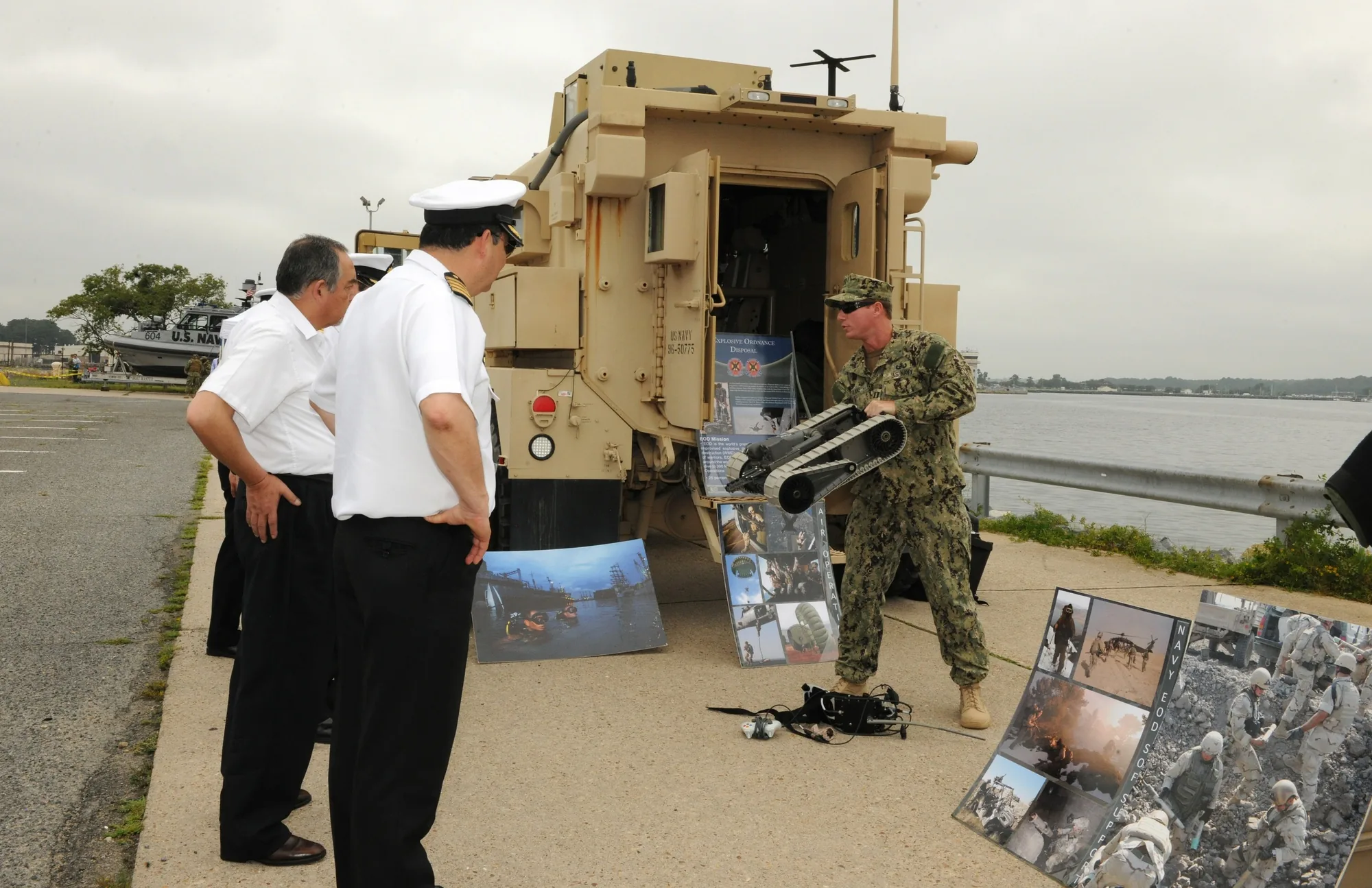
- U.S. Navy/DVIDS, PackBot transportable robotic system: featured photograph documenting a demonstration in Virginia Beach on August 8, 2012.
- Jacoff et al., Comprehensive Standard Test Suites for the Performance Evaluation of Mobile Robots: NIST research presented at PerMIS 2010, explaining distinct obstacle and mobility tasks; historical standard-development counts are not used.
Last checked: September 6, 2026.