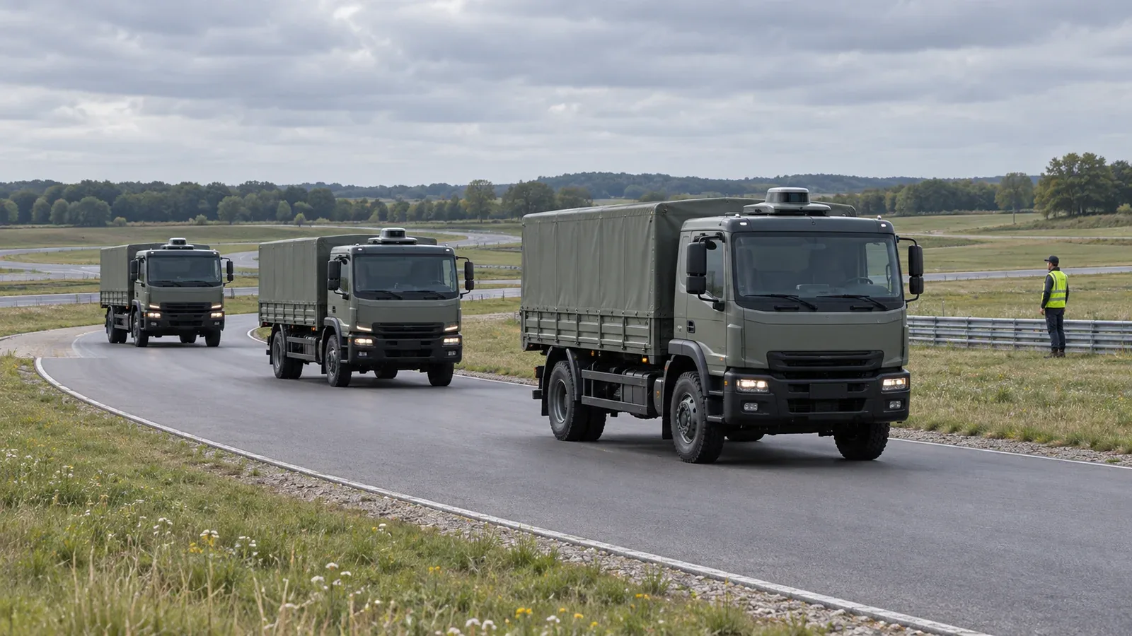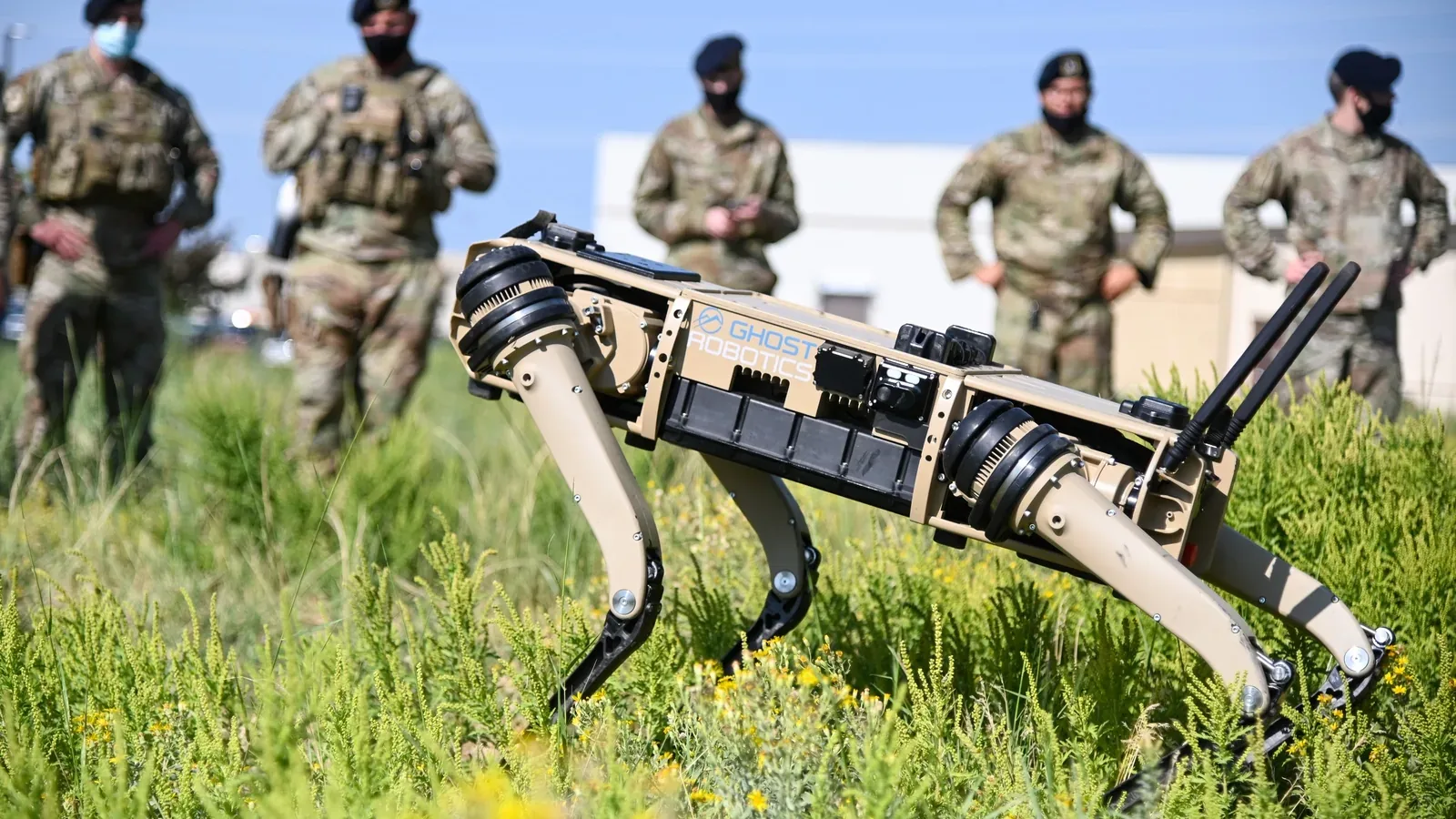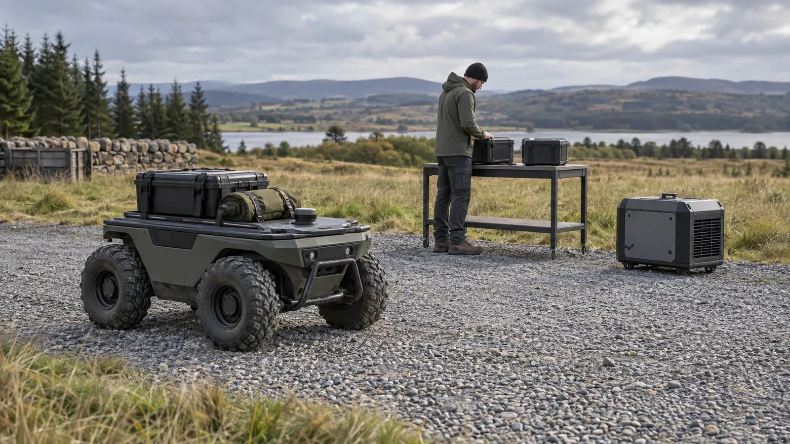
UGV power systems supply both propulsion and the equipment that makes an unmanned ground vehicle useful: computers, sensors, communications and payloads. Batteries store electrical energy; an engine-generator converts fuel into electricity; a hybrid combines sources and storage under coordinated control. The right architecture must meet peak demand, complete the mission and retain enough power for a controlled recovery.
A large battery does not by itself establish adequate peak current, and a running generator does not necessarily mean the battery is charging. Those two distinctions explain much of the difference between a promising specification and a workable vehicle.
On This Page
- Follow the power from source to payload
- Compare batteries, hybrids and generators
- Build the mission energy budget
- Specify the electrical and control interfaces
- Plan for failures and operating limits
- Choose by mission and recovery plan
Follow the power from source to payload
Start with the main direct-current, or DC, bus: the electrical distribution point between the energy source and the vehicle's loads. An electric drivetrain feeds motor controllers from this bus. DC/DC converters provide other voltages for computers, radios and sensors. Protection devices interrupt faults, while the control system determines what may operate and when. The Department of Energy's component explanation describes these roles in road vehicles; the same component distinctions help identify the boundaries in a ground robot.
Separate three functions when reading a block diagram:
- Energy supply: the battery, fuel tank and generator determine what energy is available and how it reaches the bus.
- Power distribution: converters, cables, switches and protection determine which loads can receive it.
- Energy management: control logic decides when to charge, start an engine, restrict a payload or end a task.
Battery protection is only part of that last function. The vehicle still needs to decide what to do with the battery's reported limits. The companion explanation of battery management systems for unmanned vehicles covers cell monitoring and protection in greater depth.
For a design review, request two diagrams: the power connections and the control dependencies. On the first, trace the path to each essential load. On the second, identify which controller authorizes that path and what happens if its message stops arriving. This makes a common bus, converter or controller dependency visible before anyone calls the architecture redundant.
Compare batteries, hybrids and generators
In a battery-electric UGV, onboard stored electricity supplies propulsion and payload demand. In a series hybrid, the engine drives a generator and electric motors provide traction. A parallel hybrid includes a mechanical route from the engine to the driven wheels or tracks as well as electrical assistance. DOE's hybrid architecture explanation distinguishes these paths. The word hybrid alone does not establish which arrangement a supplier uses.
An onboard generator supplying an electric drive is also different from a generator at a base station charging a parked robot. The latter supports the fleet's turnaround but does not extend the robot's untethered energy supply while it is away. Ask whether a quoted endurance figure includes an onboard engine, stationary charging, battery changes or engine-off intervals.
The following comparison is an engineering interpretation of the power paths, not a ranking of products.
| Architecture | What it offers the mission | Controlling tradeoff | Evidence to request |
|---|---|---|---|
| Battery-electric | Operation without an onboard combustion engine | Stored energy and replenishment opportunities bound the assignment | Usable energy, current limits and charger or battery-change procedure |
| Series hybrid with battery buffer | Fuel-derived electrical supply plus engine-off intervals | Generator output, battery reserve and control behavior must work together | Net electrical output, charge recovery and engine-off operating conditions |
| Generator-fed electric drive with little storage | Electrical supply while the engine runs | Less stored energy available to bridge a source interruption or load step | Load-step response and behavior after generator loss |
| Parallel hybrid | Mechanical and electrical traction paths | More interfaces to understand before assigning engine-off capability | Mechanical layout and the operating modes actually supported |
| Battery UGV with offboard generator charging | Field replenishment at a support point | The robot still needs enough onboard energy to reach that point | Charger compatibility, replenishment time and simultaneous-load limits |
Real platforms illustrate the distinction without providing a fair endurance contest. Clearpath documents the Husky A300 as using LiFePO4 batteries. Milrem's THeMIS technical page lists a diesel engine and electric generator alongside a battery option. These are examples of different arrangements, not evidence that one will complete a particular route more efficiently.
Treat silent operation as a defined mode, not a universal performance label. Specify whether the engine is off, whether the vehicle is moving and which payloads remain active. For a useful requirement, ask for the duration of that exact mode and its permitted starting battery condition. Engine-off propulsion does not establish zero sound, zero heat or an unlimited observation period.
Build the mission energy budget
Power, measured in kilowatts, describes demand at a moment. Energy, measured in kilowatt-hours, accumulates that demand over time. A mission needs both an energy calculation and a separate peak-power check.
The table below is a hypothetical five-hour assignment, not measured performance of Husky, THeMIS or another vehicle. Every power value is an assumed total at the main DC bus, including the upstream demand for payload conversion and cooling during that phase. The figures illustrate the calculation only.
| Mission phase | Duration | Assumed average bus demand | Energy |
|---|---|---|---|
| Travel to work area | 1.5 h | 1.6 kW | 2.4 kWh |
| Slow work with payload | 1 h | 0.7 kW | 0.7 kWh |
| Stationary observation | 2 h | 0.25 kW | 0.5 kWh |
| Return to support point | 0.5 h | 1.8 kW | 0.9 kWh |
| Total | 5 h | 0.9 kW time-weighted average | 4.5 kWh |
Mission energy = sum of each phase's average power × its duration = 4.5 kWh.
If, purely for this example, only 70% of nameplate battery energy is budgeted as deliverable at the bus after reserve, operating restrictions and losses, the required nameplate energy is 4.5 ÷ 0.70 = approximately 6.43 kWh. That 70% is an assumption, not a recommended universal reserve. Establish the actual usable fraction for the pack, temperature, condition and recovery requirement.
Do not subtract the same losses twice. If demand is measured at the battery terminals, downstream converter losses are already in that measurement. If demand is assembled from payload ratings, conversion losses still need accounting for. Record the measurement boundary beside the budget. The table includes the planned return journey; the separate reserve must cover whatever additional delay or recovery case the mission requires.
Stationary operation needs its own load entry. A navigation computer or observation payload may remain active after traction stops. The edge AI guide explains why onboard computing choices belong in the wider vehicle design. For power budgeting, ask for the compute and cooling demand of the actual operating mode rather than assuming parked means asleep.
A generator needs recovery margin
Suppose a hypothetical generator delivers 1.2 kW net to the bus while simultaneous vehicle demand is 0.9 kW. The ideal surplus is 0.3 kW. Replacing the example's 0.5 kWh observation interval would take 0.5 ÷ 0.3 = approximately 1.67 hours before charging losses or battery charge limits. A generator delivering exactly 0.9 kW against that load has no surplus to restore reserve.
This is why generator sizing should include the permitted recovery time after engine-off operation. The five-hour average is not enough: check each sustained phase as well. A generator below the travel load will use battery reserve during travel even if it exceeds the overall mission average. Victron's generator integration guidance, for its own inverter/charger systems, explains why total load and charging demand must be considered together and why sudden demand can trouble a generator. It illustrates the integration problem; it does not establish compatibility with a UGV.
Peak demand needs another calculation. An assumed 3 kW electrical load at a 48 V bus draws 3,000 ÷ 48 = 62.5 A. That says nothing about the permitted duration. Specify the peak's length, repetition and lowest operating voltage, then check the entire current path. An energy budget can balance while a converter or battery current limit still prevents the maneuver.
Specify the electrical and control interfaces
Record the input-voltage range, continuous and peak current, startup demand and permitted interruptions for each payload. Nominal voltage alone is not enough to approve a connection.
Clearpath's Husky A300 integration manual provides a concrete example: eight user connectors share rail limits. Its two 12 V rails each have a 5 A aggregate limit; the 24 V rail and unregulated 24–29 V battery rail each have a 5 A aggregate limit. Those are shared rail budgets, not allowances available independently at every socket. Separate expansion connections have separate rules.
Starting a load can also differ from running it. Texas Instruments' precharge application brief explains how charging a capacitive DC link before closing the main path limits inrush and avoids contact damage. That is a high-voltage design example, not a claim that every small robot uses the same contactor circuit. Ask the supplier how its actual architecture manages startup current and detects an unsuccessful start.
The control interface should distinguish a request from a confirmed result. A generator-start command does not prove that usable electrical output has appeared. Victron's generator start/stop documentation distinguishes warmup, running and cooldown states and describes detecting absent generator input. For a UGV, request an equally explicit account of when loads may rely on the source and what happens when that confirmation is absent.
Useful interface questions include who sets charge and discharge limits, how old a measurement may become before it is rejected, and which loads lose power during a propulsion stop. Component replacement also needs behavioral agreement, as the open architecture explainer discusses. A matching connector or communications bus does not settle those questions.
Plan for failures and operating limits
Recovery should be specified while the architecture is still being chosen. The following are proposed engineering review scenarios, not reports of tests performed on any named product.
| Scenario | What to establish in the proposed design |
|---|---|
| Generator fails to start | Which loads can continue, how remaining reserve is reported and when the task must end |
| Repeated high traction demand | Whether the battery, converter and generator recover between peaks without progressively exhausting reserve |
| Payload shorts or overloads | Whether its protection isolates that branch and which essential functions remain available |
| Battery telemetry stops updating | How stale information is identified and which conservative operating state follows |
| Main bus or common converter fails | Whether any claimed backup actually has an independent path to the required load |
| Vehicle stops on a slope | How the specified stopping and holding behavior is maintained under the relevant power fault |
Regenerative braking introduces another limit: the battery must be able to accept returned energy. The Husky A300 user manual gives temperature- and state-of-charge-dependent restrictions for hill operation. Its guidance illustrates why the charge side of the power system matters during a descent. Use the actual vehicle's limits rather than transferring Husky's thresholds to another platform.
Replenishment assumptions deserve the same scrutiny. The Husky manual states that its packs are not hot-swappable. It also explains that a connected charger can supply the robot while the batteries still discharge if total demand exceeds charger output. A charging connection therefore does not, by itself, demonstrate either continuous operation or a net increase in stored energy.
For an engine-equipped design, make cooling, exhaust routing, fuel servicing and maintenance access part of the requested installation documentation. DOE includes exhaust and thermal systems among hybrid components; leaving them outside the integration boundary understates what must fit on the vehicle. Do not infer an environmental rating or suitability for an enclosed work area from the drivetrain label.
Choose by mission and recovery plan
For a bounded inspection or research task with predictable access to charging, first evaluate whether a battery system can complete the full assignment and recovery within its energy and current limits. For longer remote work with permitted engine operation, evaluate whether a hybrid restores reserve quickly enough between engine-off intervals. For stationary sensing, define the payload and computing load before choosing the battery or generator size.
These are starting points for evaluation, not product recommendations. Ask the supplier to return a mission power budget, the electrical and control interface limits, and a demonstration plan covering the difficult transitions. Include depleted reserve, generator startup, payload activation and the specified recovery behavior. Choose the architecture that can explain and substantiate those transitions under the intended conditions, rather than the one with the largest isolated battery or endurance number.
Sources
- DOE Alternative Fuels Data Center: Hybrid Electric Vehicles. Government educational reference for series and parallel propulsion paths.
- DOE Alternative Fuels Data Center: How Do Hybrid Electric Cars Work?. Government reference for power electronics, conversion, storage and thermal-system roles.
- Milrem Robotics: THeMIS. Manufacturer reference establishing the diesel-generator and battery architecture example.
- Clearpath Robotics: Husky A300 User Manual. Manufacturer instructions for battery configuration, regenerative limits and charging behavior.
- Clearpath Robotics: Husky A300 Integration. Manufacturer documentation for shared payload rails and electrical interfaces.
- Texas Instruments: SLVAFB0 precharge application brief. Component application guidance on capacitive inrush and precharge sequencing.
- Victron Energy: MultiPlus Generator FAQ. Manufacturer guidance on generator output, transient loads and simultaneous charging.
- Victron Energy: GX Generator Auto Start/Stop. Manufacturer documentation for generator states and input detection.
Last checked: September 10, 2026.