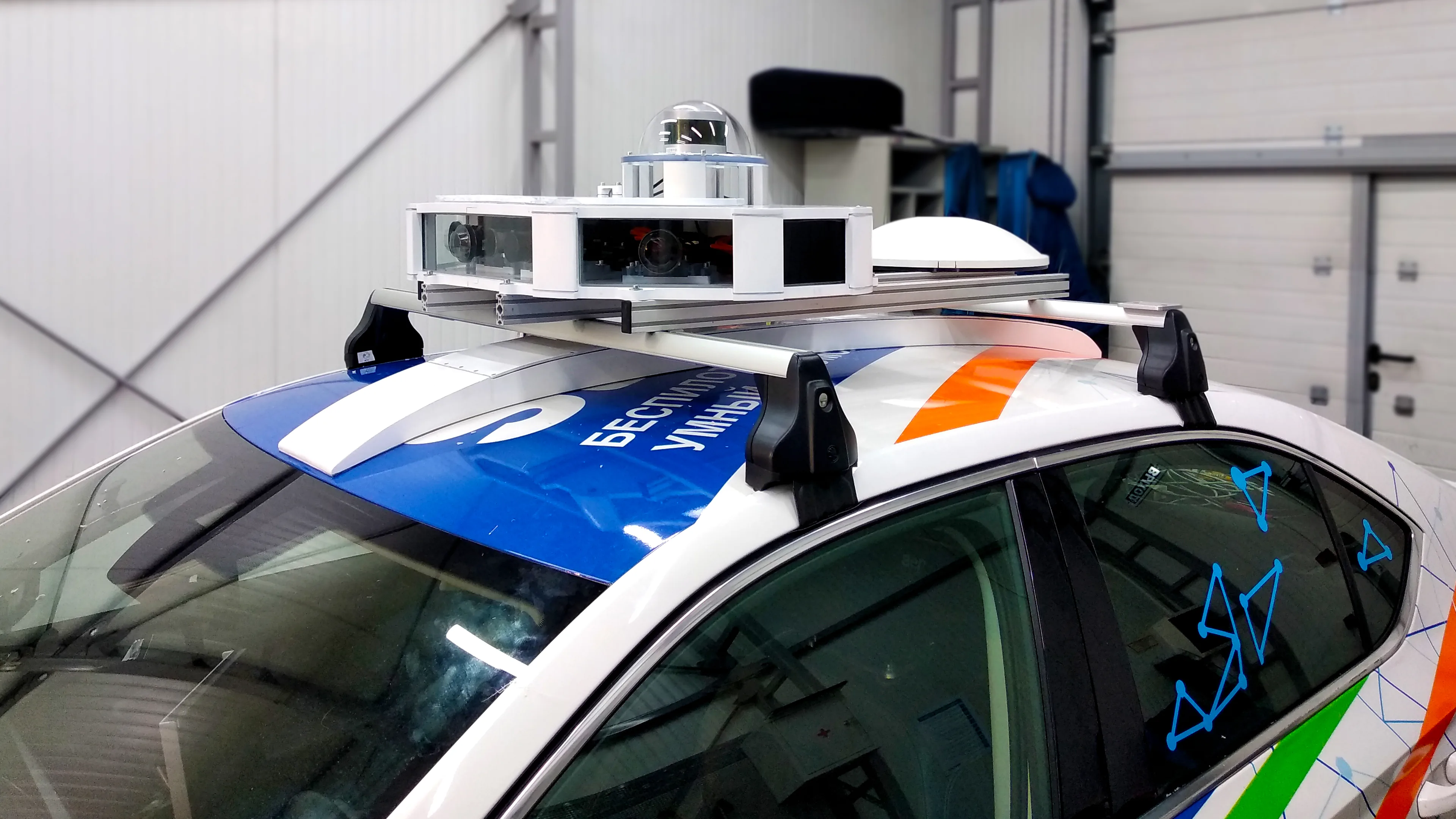
Radar measures distance and motion toward or away from a sensor. LiDAR measures the three-dimensional arrangement of reflecting surfaces. Cameras capture the visual detail used to recognize lane markings, signs, signals, and objects. For an autonomous vehicle, the useful choice depends on which information the mission needs, where each sensor loses reliability, and how the complete system responds when that happens.
For road vehicles, combining these inputs can provide complementary observations. It also creates calibration, timing, computing, and maintenance work. A sensor list alone cannot establish whether a vehicle can operate safely in its intended conditions.
The comparison below covers outward-looking perception for autonomous ground vehicles, principally road vehicles. “Camera” means conventional visible-light imaging; thermal cameras and active depth cameras have different capabilities. Navigation, planning, braking, and steering remain separate parts of the vehicle system.
On This Page
- Compare what each sensor measures
- Follow the measurement into software
- Read performance specifications in context
- Account for weather and dirty sensors
- Integrate the sensors into one vehicle
- Match the architecture to the mission
Compare what each sensor measures
The central distinction is the information available before perception software interprets the scene.
| Decision criterion | Radar | LiDAR | Visible-light cameras |
|---|---|---|---|
| Physical input | Reflected radio waves | Reflected laser light | Light focused onto an image sensor |
| Characteristic output | Range, direction, and radial velocity; representation varies | Range samples assembled into a point cloud, often with return intensity | Images; depth and motion require additional estimation |
| Main contribution | Closing motion and an observation channel with different weather sensitivities from optical sensors | Measured scene geometry | Appearance, color, markings, and visual context |
| Important limitation | Reflections can create false detections; angular detail depends on the radar | Returns depend on the target and atmosphere; a point cloud is not an object label | Visibility and image quality constrain recognition; depth depends on the method |
| Useful question for integration | Are raw measurements, detections, or tracked objects available? | What region and point timestamps does a scan cover? | What exposure, calibration, and depth-estimation method are used? |
Source basis: the Texas Instruments radar primer, the LiDAR technical review, the radar perception review, and OpenCV stereo documentation. Integration questions are editorial synthesis. This is a comparison of sensing principles, not a benchmark of interchangeable products.
Follow the measurement into software
Radar: range and radial velocity
Frequency-modulated continuous-wave, or FMCW, radar transmits frequency sweeps called chirps. Electronics compare transmitted and received signals to estimate range. Phase changes across chirps reveal radial velocity, while measurements across antennas support angle estimation. TI explains these measurement stages.
Radial velocity is motion along the line between sensor and target. A target moving across that line can have little radial motion at a particular instant despite moving quickly. Tracking and vehicle-motion estimation are still needed to recover a fuller picture of traffic motion.
Radar software may process a multidimensional measurement array, a detection list, or tracks already produced inside the sensor. Those interfaces leave different amounts of information available for downstream interpretation. The radar review by Srivastav and Mandal describes this range of representations and processing approaches.
LiDAR: geometry from laser returns
A pulsed time-of-flight LiDAR estimates distance from the laser's round trip. Its emitter, optics, receiver, and scanning or illumination arrangement determine where measurements are taken. Software transforms those returns into a point cloud, then detects surfaces and objects and tracks changes.
Scanning and ranging are separate design choices. A rotating sensor, a beam-steering device, and a flash architecture do not sample the scene identically. Nor is all LiDAR limited to distance measurements: coherent FMCW LiDAR can also measure Doppler velocity. These distinctions are described in Li and Ibanez-Guzman's technical review.
Cameras: appearance plus estimated depth
A camera supplies an image rather than a direct per-pixel laser range. A vision system can estimate depth from learned scene relationships, motion across frames, or multiple viewpoints. With a calibrated stereo pair, corresponding points appear at different horizontal positions; this disparity supports geometric depth estimation.
OpenCV's stereo tutorial relates depth to focal length, camera separation, and disparity. Farther objects produce smaller disparity, making precise matching increasingly important. A stereo camera specification therefore needs more than pixel count: baseline, calibration, usable overlap, and the matching algorithm also matter.
Read performance specifications in context
Separate range accuracy, the error in a distance estimate, from range resolution, the ability to distinguish nearby returns. Also ask about angular resolution, which determines whether neighboring directions can be separated. TI's radar primer shows why a fine range resolution does not, by itself, establish fine angular discrimination. Radar measurement fundamentals.
For LiDAR, an advertised maximum distance needs its target reflectivity and measurement conditions. The underlying return depends on surface properties, incidence angle, and transmission through the atmosphere. A strong return from a favorable surface does not establish detection of every small or weakly reflecting obstacle at that distance. LiDAR return-signal model.
For camera systems, distinguish identifying a large object from recognizing a small signal or estimating its distance. The same image stream can support those tasks with different confidence. Waymo's description of its sixth-generation system illustrates the separation: it describes associating LiDAR distance measurements with camera imagery and using different sensors for overlapping coverage. That is one developer's architecture, not a universal performance rating.
For a supplier comparison, request results for the same target, distance, lighting, weather, vehicle speed, and error definition. Include missed objects, false detections, and the delay before a usable track appears. Specify near-field blind areas as well as maximum distance. Comparing one sensor's best-case distance with another system's object-recognition range will not answer the mission question.
Account for weather and dirty sensors
Darkness and fog are different problems. Radar and LiDAR provide their own transmitted energy, while a conventional camera relies on available illumination. But LiDAR still uses light: atmospheric particles can scatter its signal and produce backscatter or weaken useful returns.
In Seeing Through Fog Without Seeing Fog, Bijelic and colleagues studied multimodal perception under changing illumination and adverse weather. Their fog experiments showed different degradation across optical sensors and radar. The work also showed why a fusion method must respond to uneven sensor quality. It does not establish that any production sensor combination can operate through every weather condition.
Radar's relative resilience to fog does not remove other failure modes. Multiple reflections from walls, vehicles, or guardrails can produce apparent objects or displaced returns. The radar perception review describes these multipath effects and the difficulty of separating them from real objects.
Sensor cleanliness is another system requirement. Waymo describes integrated camera cleaning and complementary sensing in its sixth-generation hardware account. The practical implication is to evaluate contamination detection, cleaning, and recovery along with the sensor itself. An operating plan should define what the vehicle does when the view remains inadequate after cleaning.
Integrate the sensors into one vehicle
Align both position and time
Spatial calibration establishes how measurements from different mounting positions relate. Temporal calibration establishes when those measurements occurred. A geometrically correct projection can still associate the wrong observations if the vehicle or target moved between captures.
Sommer and colleagues' temporal-calibration research distinguishes sensor timing from data-arrival delays and demonstrates why device-specific timing behavior matters. For integration, ask what each timestamp denotes, how clocks relate, and how the software handles samples acquired across a scan or exposure interval.
Consider an illustrative timing calculation. With an assumed relative speed of 20 metres per second and an uncorrected offset of 50 milliseconds, motion during the offset is:
Displacement = speed × time = 20 m/s × 0.050 s = 1 metre.
This is an editorial scenario using assumed inputs, not a measured sensor error. It shows why synchronizing file arrival times is insufficient. The effect on a fused estimate depends on motion direction, processing, and compensation.
Choose where fusion happens
Fusion can combine measurements, learned features, or independently estimated objects and tracks. Earlier combination retains opportunities to use detail across modalities; later combination depends on what each separate detector has already retained. The fog study compares different fusion arrangements and adaptive treatment of sensor quality.
Specify the behavior when inputs disagree. Does an uncertain camera classification suppress a radar detection? Can an obstacle remain in the world model without a confident class label? What happens when a sensor stops updating? These are review questions for the implemented software, not answers supplied by choosing three sensor types.
Specify the data interface and computing load
Ask what crosses the sensor's connector, what arrives at the perception application, and what the vehicle records. A camera image stream, a LiDAR point cloud, and a radar track list are different processing commitments. A track list may simplify the receiving application while leaving less access to the measurements behind a detection. Raw inputs leave more processing decisions with the integrator. The radar review's discussion of data representations makes this interface distinction particularly relevant when comparing radar suppliers.
An illustrative camera data budget shows why the interface deserves an explicit calculation. Assume one uncompressed stream with 1,920 by 1,080 pixels, three bytes per pixel, and 30 frames per second:
Payload rate = 1,920 × 1,080 × 3 × 30 = 186,624,000 bytes per second, or approximately 186.6 MB/s and 1.49 gigabits per second.
These are assumed format settings, not specifications for a named camera. The result excludes protocol overhead and metadata and uses decimal units. Compression or a different pixel format changes the result. It is a transport calculation, not an estimate of how much computing power the perception model needs.
For a proposed installation, repeat the calculation using its actual delivered formats and simultaneously active streams. Ask separately for peak traffic, sustained recording throughput, processing delay, memory needs, and behavior when a consumer falls behind. A nominal frame rate does not tell the buyer whether the vehicle receives fresh information promptly or processes an accumulating queue.
Budget the complete installation
Request a system budget covering sensors, mounting, wiring, cleaning, power, cooling, computation, recording, calibration, replacement, and revalidation. Compare the same coverage and delivered outputs. A purchase-price comparison that excludes perception computing or recurring calibration can select the wrong architecture even when its component prices are accurate.
Also review shared dependencies. Adding a second observation channel does not establish independence from a shared power supply, processor, clock, or obscured mounting location. Ask the integrator to demonstrate loss and recovery of each channel and identify which functions remain available.
Make that demonstration specific. Request a controlled test with an interrupted stream, then one with a stream that continues arriving but carries stale timestamps. Ask how the vehicle distinguishes an empty scene from an unavailable observation, how it reports uncertainty to planning software, and which recovery checks it performs before restoring a function. Include a post-maintenance calibration check in the handover requirements. These questions expose behavior that a clean-weather object-detection demonstration may leave unanswered.
Match the architecture to the mission
These starting points are editorial interpretations of the sensing and integration evidence above. They identify what to evaluate, rather than certify a particular vehicle.
| Mission | Useful emphasis | Decisive question before selection |
|---|---|---|
| Mixed urban traffic | Camera interpretation of road meaning, geometric observations, and tracking across complementary inputs | Can the system handle a partly hidden road user, conflicting observations, and a change in visibility? |
| Faster road travel | Early usable tracks, radial-motion information, and perception latency | Is the demonstrated detection and response distance adequate for the vehicle's actual stopping behavior? |
| Low-speed industrial transport in a controlled area | Geometry and near-field coverage, with vision where labels or visual cues matter | Does the test include the smallest relevant obstruction and the actual lighting and surface conditions? |
| Outdoor operation with frequent fog or contamination | Radar as a complementary channel, sensor-health monitoring, and cleaning | When must the vehicle slow, stop, or leave autonomous operation because the remaining information is insufficient? |
A camera-led design should demonstrate depth and recognition performance throughout its permitted conditions. A LiDAR-led design still needs to interpret geometry and supply whatever visual meaning the mission requires. A radar-led design must address angular detail, false returns, and interpretation. A fused design must demonstrate that calibration, timing, software, and maintenance preserve the intended benefit.
Start the specification with the objects and road features the vehicle must understand, the conditions it may encounter, and the time available to respond. Then select the sensing architecture and require demonstrations against those needs. The strongest choice is the one whose measured limitations fit the mission and whose behavior outside those limits is defined.
Sources
- Texas Instruments: The fundamentals of millimeter wave radar sensors. Manufacturer technical primer on FMCW range, velocity, and angle measurement.
- Li and Ibanez-Guzman: Lidar for Autonomous Driving. Technical research review covering ranging, scanning architectures, perception, and physical limitations.
- Srivastav and Mandal: Radars for Autonomous Driving. Research review of radar data representations, perception methods, and multipath challenges.
- OpenCV: Depth Map from Stereo Images. Software documentation explaining the geometry behind stereo disparity and depth.
- Bijelic and colleagues: Seeing Through Fog Without Seeing Fog. Experimental research on multimodal perception and sensor fusion under adverse weather.
- Sommer and colleagues: A Low-Cost System for High-Rate, High-Accuracy Temporal Calibration for LIDARs and Cameras. Experimental research on measurement timing and sensor-to-computer delays.
- Waymo: Beginning fully autonomous operations with the 6th-generation Waymo Driver. Developer account of a specific multimodal architecture, overlapping coverage, and sensor cleaning; not an independent comparison.
Last checked: September 8, 2026.