A UAS payload interface is the set of connections that lets mission equipment work with an unmanned aircraft: its mounting, power supply, communications, timing, and control software. A compatible connector is only one part of that interface. The aircraft, payload, and operator software must also agree on what commands mean, how results return, and what happens when a connection fails.
For integration, ask two questions separately: Can the aircraft carry and operate this equipment? And can the complete system deliver the required mission data or action? A camera can power up and respond to commands while its images remain inaccessible or incorrectly timed.
On This Page
- Where the payload connects
- Physical installation and power
- Transport and protocol compatibility
- Commands, ownership, and feedback
- Timing and data performance
- Failure modes to check
- Match the interface to the application
Where the payload connects
A useful architecture separates the aircraft's flight controller, the payload, an optional companion computer, and the ground station. The flight controller handles aircraft control. A companion computer can host payload software and route communications; the ground station provides operator control and displays results. Some payloads contain enough processing to operate without a separate companion computer.
There can be several paths between those components. One carries commands and status. Another carries images or other mission data. A trigger or timing connection may run alongside both. Electrical power and the mechanical mounting remain separate design responsibilities even when one docking assembly combines them.
The PX4 v1.16 companion-computer guide illustrates serial and supported Ethernet connections to the flight controller, with software on the companion responsible for communication and routing. The MAVLink Camera Protocol v2 separately describes camera capabilities, capture status, and video-stream information. These are examples of the division of responsibilities, rather than a mandatory architecture for every aircraft.
For a particular integration, put those paths into an interface control document: a shared description of the connections and behavior both sides must implement. Name the hardware revisions, firmware versions, connector pin assignments, message definitions, and software responsible for each function. “Supports the payload” is too broad to resolve a disagreement between suppliers.
Physical installation and power
Start with the installed assembly, including its bracket, cables, and any computer or converter. The useful questions are whether it stays within the aircraft's mounting and balance limits, leaves the sensor's view clear, permits the intended gimbal movement, and provides a heat-removal path. Record the mounting datum so sensor alignment can be reproduced after removal.
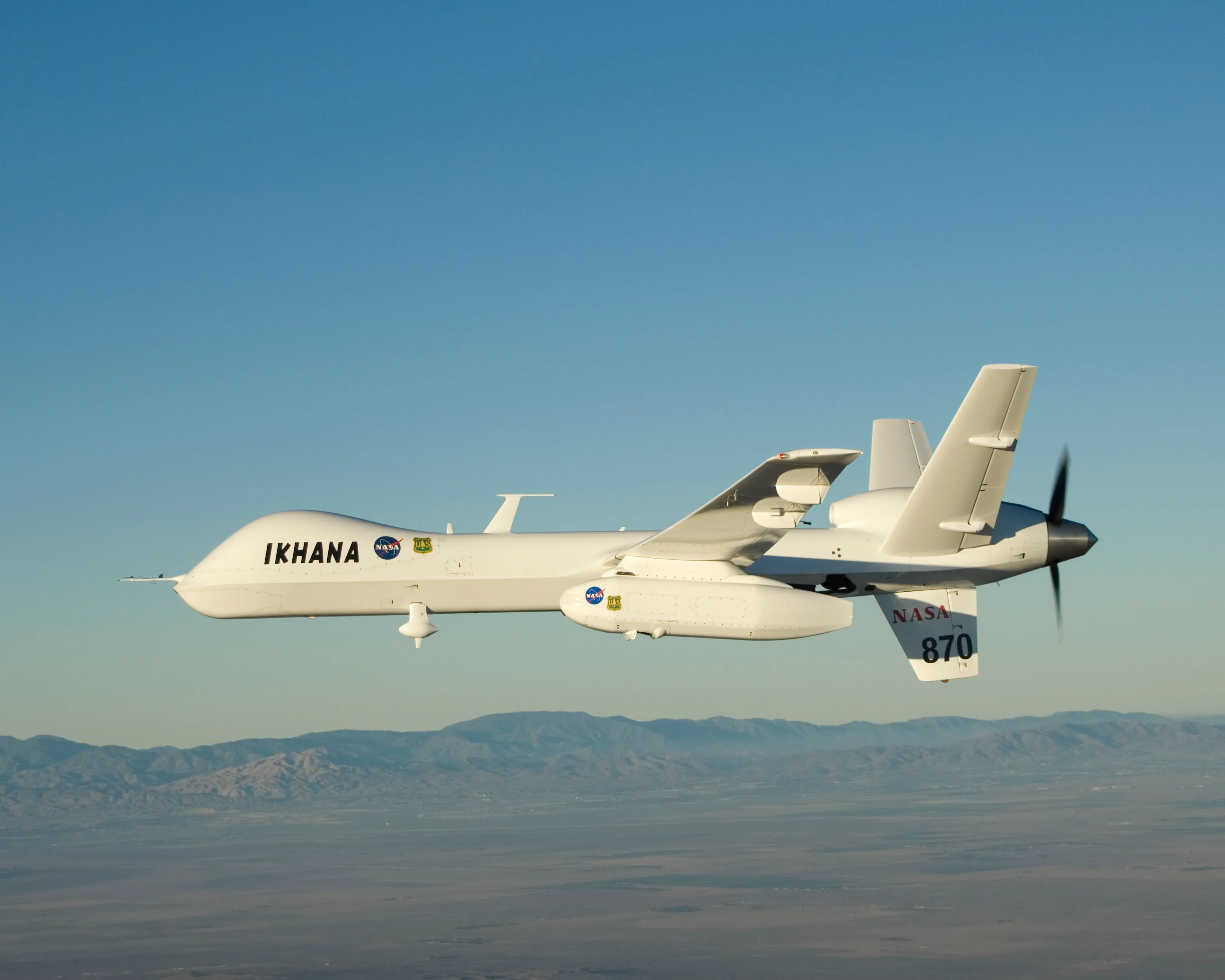
NASA's Ikhana aircraft description explains that sensors were integrated into wing-mounted pods where possible to reduce aircraft downtime and support reconfiguration. A removable pod packages an installation boundary; it does not establish that another aircraft accepts the same pod.
Power compatibility also extends beyond nominal voltage. Obtain the permitted input range, continuous and peak load, startup behavior, grounding arrangement, and response to a power interruption. DJI's Payload Development Criterion, dated July 2, 2026, lists different electrical provisions for different ports and aircraft. It also describes startup protection that can shut down the supply when the attached load capacitance is excessive. Those are platform-specific requirements, not universal UAS power limits.
Check signal voltage independently of supply voltage. The PX4 v1.16 companion guide warns that a 1.8 V companion-computer UART can be damaged by 3.3 V signaling. UART means universal asynchronous receiver/transmitter; naming that interface does not establish electrical compatibility.
Thermal and interference design belong in the installation too. The DJI E-Port V2 Development Kit instructions call for heat dissipation and a metal shielding cover when its development board is integrated into a payload product. For that board, an exposed bench connection is therefore an incomplete installation. Other hardware needs its own applicable thermal and shielding requirements.
Transport and protocol compatibility
An interface label may identify a connector, an electrical link, or a software protocol. Treating these as interchangeable is a common source of integration mistakes.
The following table distinguishes what each layer contributes. Its examples draw on PX4's companion guidance, the MAVLink camera protocol, and DroneCAN's basic concepts and hardware recommendations, checked September 6, 2026. The verification questions are engineering synthesis.
| Interface layer | What it establishes | What still needs agreement |
|---|---|---|
| Connector and cable | Physical mating and assigned conductors | Pinout, signal levels, power source, shielding, retention |
| UART serial link | A path for serial communication | Baud rate, framing, flow control, and the messages carried |
| CAN bus | Shared communications infrastructure | Matching application protocol, data types, node identities, and bus configuration |
| Ethernet connection | Network connectivity where supported | Addressing, transport, service discovery, routing, and application behavior |
| MAVLink camera service | Defined camera commands and status exchanges | Implemented capabilities and access to the actual image or video stream |
DroneCAN demonstrates why “CAN-compatible” is incomplete. It defines data structures, message broadcasting, services, and functions such as node health monitoring above the CAN transport. Two devices with CAN wiring still need compatible software behavior to exchange useful information.
Its hardware recommendations also specify connector-dependent power arrangements, cable practices, and bus parameters. Do not transfer one connector's electrical assumptions to another merely because both carry CAN. In a shared bus, a change to one payload's wiring can become a system integration issue.
Choose the transport from the data and installation requirements, then verify the application protocol on it. A gateway can translate between interfaces, but its configuration, restart behavior, and interpretation of messages become additional parts of the system to qualify.
Commands, ownership, and feedback
Discovery should establish what a device actually supports before the operator sends commands. In MAVLink Camera Protocol v2, the controller requests camera information and reads capability flags. Capture, recording, and streaming are distinct capabilities. Acknowledging a capture request is also distinct from reporting an image capture or reporting storage status.
Keep the control loop visible: request an action, receive its command result, and inspect the resulting device state. A successful command exchange alone cannot demonstrate that a usable mission product reached storage or the operator.
For a gimbal, there is another question: Who currently controls its pointing? The MAVLink Gimbal Protocol v2 separates the gimbal device from a gimbal manager. The manager arbitrates commands from sources such as the ground station, mission controller, and companion computer. It may reside on the autopilot, an onboard computer, or an integrated camera/gimbal.
That distinction matters when automatic tracking and manual control coexist. Verify the handover in both directions, along with angle limits, device identity, and status reporting. The protocol also distinguishes yaw relative to the vehicle from yaw relative to Earth. A numerically valid angle in the wrong reference frame can point the sensor somewhere the operator did not intend.
An interface specification must therefore describe units and reference frames as carefully as message names. Record which component translates between aircraft attitude, gimbal orientation, and the mission's pointing request.
Timing and data performance
For mapping or synchronized sensing, the time a message arrives is not necessarily the time the sensor acquired its measurement. Sending a camera trigger, beginning an exposure, and receiving a file are different events.
The archived PX4 v1.12 Camera Trigger guide provides a concrete implementation example: camera feedback can identify the capture event, and PX4 uses capture timing when that feedback is configured instead of relying on the trigger timestamp. This illustrates the distinction; its historical pin assignments and settings should not be applied to a different board or firmware release without the matching manual.
Clock synchronization solves a related problem. The MAVLink Time Synchronization Protocol v2 estimates the offset between component clocks using repeated timestamp exchanges. Link congestion and processing time affect the estimate. A shared clock basis does not, by itself, identify exposure timing or remove sensor-processing delay.
For a simple illustrative calculation, assume straight flight at 10 m/s and a 20 ms error in associating an image with aircraft position. The along-track displacement is:
Displacement = speed × timing error = 10 m/s × 0.020 s = 0.20 m.
This is arithmetic for the stated assumptions, not a measured camera error or total mapping accuracy. It excludes attitude error, sensor alignment, terrain geometry, and other contributions. It shows why a timing requirement should follow the mission's tolerance rather than the mere presence of timestamps.
Throughput needs similar precision. Specify separately the payload's data production, onboard recording, and live downlink needs. MAVLink's camera service reports stream configuration, but does not define a mechanism for precisely frame-synchronized video metadata. A video picture and a nearby telemetry update are not automatically a synchronized measurement pair.
Local recording can preserve a mission product that does not need immediate delivery, while a live inspection operator needs sufficiently fresh video. Higher resolution and less compression may increase data demand; accepting more compression or a reduced preview can change what the operator can judge. Specify those choices against the inspection task, then test streams, control traffic, and recording together. Nominal connection speed alone does not tell the operator how old a displayed frame is.
Failure modes to check
The useful boundary is between loss of a payload function and loss of something the aircraft depends on. Establish which resources are shared, and which failures can propagate across them.
DroneCAN's hardware guidance explicitly calls for protection so a short in a bus-powered device does not collapse the entire bus supply, and for preventing a failure from propagating between redundant power inputs. That is a concrete example of designing failure containment into the interface.
These checks synthesize the cited power, bus, camera, gimbal, and timing documentation. They are proposed integration checks, not reported test results or a substitute for aircraft-specific qualification.
| Failure or symptom | What to inspect | Behavior to establish |
|---|---|---|
| Payload does not start or resets | Supply at the payload, startup load, power protection | Clear fault indication and controlled recovery without disrupting shared systems |
| Device appears but a function fails | Firmware, capability response, addressing, command result | Unsupported functions remain unavailable and errors reach the operator |
| Camera responds but no useful imagery arrives | Capture status, storage, stream address and routing | Distinguish capture, recording, and downlink failures |
| Gimbal moves unexpectedly | Control owner, reference frame, limits, stale requests | Predictable transfer of control and defined response to lost commands |
| Data remains present but becomes mistimed | Acquisition timestamp, clock offset, synchronization status | Mark degraded timing rather than silently treating it as valid |
| Another bus device fails after a payload fault | Shared supply, wiring, protection, interface isolation | Contain the fault and identify affected functions |
Repeat the relevant checks after a payload restart and after a connection is restored. Record whether discovery, control ownership, and timing must be established again. Define whether an interrupted action can resume, needs a new request, or requires operator intervention; do not let reconnecting silently repeat an actuation. A recovery sequence that works only from a clean startup leaves an important operating case unanswered.
Match the interface to the application
Different missions emphasize different parts of the same interface:
- Still-image mapping: prioritize capture feedback, image identity, timing, and association with aircraft position. Verify the stored files as well as the trigger count.
- Live visual inspection: prioritize controllable pointing, understandable camera state, video freshness, and operator handover. Recording and live viewing can have different success conditions.
- Scientific sensing: prioritize the instrument's power and installation requirements, acquisition timing, and preservation of its data. Ikhana's documented removable sensor pods illustrate how packaging can support research reconfiguration.
- Winches and grippers: prioritize action completion and fault state. MAVLink's Payload Protocols defines commands for these payload classes, but a command definition does not prove that a particular mechanism has completed its motion.
Before accepting an integration, ask for the interface document, the exact supported hardware and software configuration, and a demonstration of the required mission function with representative data loads and relevant faults. Retain the resulting configuration with the aircraft and payload records. The strongest compatibility statement identifies what works, under which conditions, and how the system behaves when it stops working.
Sources
- PX4 v1.16: Using a Companion Computer with Pixhawk Controllers. Implementation manual for serial/Ethernet connections, routing responsibilities, and signal-level compatibility.
- MAVLink Camera Protocol v2. Protocol documentation for discovery, capabilities, capture and storage status, streams, and video-metadata limitations.
- NASA: Ikhana. Aircraft program description documenting sensor integration in removable wing-mounted pods.
- DJI: Payload Development Criterion. Manufacturer requirements, dated July 2, 2026, for platform-specific electrical and installation compatibility.
- DJI E-Port V2 Development Kit Product Information. Hardware instructions covering installation, heat dissipation, shielding, and output constraints.
- DroneCAN: Basic Concepts. Protocol specification describing data structures, services, and node functions above CAN transport.
- DroneCAN: Hardware Design Recommendations. Connector, wiring, power-protection, and bus-design guidance.
- MAVLink Gimbal Protocol v2. Protocol documentation for manager/device roles, control ownership, status, and pointing reference frames.
- PX4 v1.12: Camera Trigger. Archived implementation example distinguishing trigger timing from capture feedback.
- MAVLink Time Synchronization Protocol v2. Protocol documentation explaining estimated clock offsets and effects of communication delays.
- MAVLink Payload Protocols. Definitions of command interfaces for payload classes including winches and grippers.
Last checked: September 6, 2026.