Visual-inertial odometry (VIO) estimates a moving system's position, orientation, and velocity by combining camera images with an inertial measurement unit (IMU). It provides motion estimates relative to a local reference, making it useful where satellite navigation is unavailable. It does not, by itself, establish a geographic position or prevent accumulated drift. PX4's VIO overview describes this local navigation role.
For an unmanned-system integrator, the decisive question is whether that estimate remains timely and trustworthy through the intended motion and environment. A plausible trajectory on a screen is only the beginning: initialization, coordinate frames, uncertainty, and recovery behavior determine whether the rest of the vehicle can use it.
On This Page
- What the camera and IMU each contribute
- How measurements become a motion estimate
- Why initialization and drift still matter
- Calibrate the sensor assembly and its clocks
- Define the interface to the vehicle
- Choose tradeoffs for the operating environment
- Test failures as well as nominal accuracy
- Decide what the mission needs beyond VIO
What the camera and IMU each contribute
A camera observes the scene. Tracking the same features across images constrains how the camera moved relative to those features. A single camera has no direct distance measurement: without another scale reference, a reconstruction can preserve shape while expressing distances in arbitrary units. Combining vision with inertial measurements can recover metric scale when the motion supplies sufficient information, as explained in the VINS-Mono research paper.
An IMU measures angular rate with gyroscopes and specific force with accelerometers. Specific force is not already world-frame vehicle acceleration. The estimator must account for attitude, gravity, sensor biases, and noise before using it to update velocity and position. OpenVINS' inertial propagation derivation makes those dependencies explicit.
Inertial propagation predicts motion between images, while visual observations constrain the evolving estimate. A bias is a persistent sensor offset; integrating an uncorrected offset produces growing error. An IMU can therefore bridge short interruptions in visual tracking, but its presence does not make an extended camera outage harmless.
VIO's outputs describe the vehicle's motion. They do not automatically identify a safe landing zone, classify obstacles, or generate a collision-free route. Those are separate perception and planning responsibilities, even when they share the cameras or computer.
How measurements become a motion estimate
A typical implementation connects three functions:
- Visual processing tracks image features, rejects inconsistent matches, and maintains observations across frames.
- Inertial processing propagates motion and uncertainty between camera measurements. Optimization systems may use IMU preintegration, which summarizes a span of inertial readings without repeatedly integrating the full sequence during every solve.
- State estimation combines the constraints to update pose, velocity, biases, and any additional estimated quantities.
The VINS-Mono paper describes a tightly coupled sliding-window optimizer: visual and inertial measurements constrain the same estimation problem over a limited recent history. A loosely coupled design combines estimates from separate subsystems. These terms describe the level of fusion; they are not quality ratings.
Filtering is another approach. OpenVINS implements a multi-state constraint Kalman filter (MSCKF), using observations across stored camera poses to constrain motion. Both filtering and optimization implementations can support calibration estimation and additional features. Compare the actual configuration, processing load, and failure handling rather than assuming one algorithm family always wins.
Some packages contain more than odometry. The VINS-Mono implementation also includes loop detection, relocalization, and pose-graph optimization. These functions recognize revisited places and revise trajectory relationships. When evaluating a demonstration, establish which of these capabilities were enabled.
Why initialization and drift still matter
Initialization establishes a usable starting state. In monocular VIO, scale and other quantities may need motion to become distinguishable from one another. A startup routine that works during varied handheld movement is not automatically suitable for a vehicle that starts motionless or drives almost entirely in a plane.
Static initialization and complete observability are different issues. OpenVINS documents both static and dynamic initialization; that does not mean every calibration parameter becomes observable while stationary. Its inertial-model documentation warns that restricted motion can undermine online calibration. The practical requirement is a documented startup procedure that the actual platform can perform.
Even with useful motion, unaided VIO cannot infer its absolute starting translation or global heading solely from local camera and IMU observations. OpenVINS' observability discussion identifies the unobservable directions as global translation and rotation about gravity. Gravity helps establish roll and pitch; it does not supply north.
This also matters for uncertainty. An estimator can become overconfident if its mathematics appears to gain information in directions that the sensors cannot actually constrain. A small reported covariance, the numerical representation of uncertainty, is not independent proof of accuracy.
Loop closure can reduce accumulated inconsistency when the system recognizes a previous location. Global localization adds a relationship to an external reference, such as a known map. Neither capability should be inferred from the label “VIO.”
The ROS REP 105 coordinate-frame convention captures a useful distinction: an odom estimate is continuous but may drift, while a map estimate can correct drift through discrete updates. Controllers and planners must know which behavior they receive.
Calibrate the sensor assembly and its clocks
Three calibration problems deserve separate attention:
- Intrinsics: the camera's projection and distortion model, plus the IMU's relevant sensor characteristics.
- Extrinsics: the camera-to-IMU rotation and translation, and the assembly's relationship to the vehicle body.
- Timing: the relationship between image exposure times and inertial measurement times.
Kalibr's camera-IMU documentation describes spatial and temporal calibration and calls for motion exciting the IMU axes, low motion blur, and low-jitter timestamps on a common clock. Its output includes estimated transforms, time shifts, and diagnostic plots. Retain the report alongside the configuration used on the vehicle.
A fixed time offset and variable delivery delay are different problems. Camera and IMU data may agree internally while the finished estimate arrives late at the flight controller. Treat sensor synchronization and downstream estimate latency as separate checks. A larger delay setting cannot repair random timestamp jitter or missing measurements.
Match calibration to the installed assembly. Record the sensor identities, lens settings, image mode, mounting transforms, and calibration date. After a hardware or mounting change, verify that the retained calibration still describes what is installed. This is an integration recommendation, not a claim that a particular tool automatically detects every change.
Define the interface to the vehicle
An interface must specify more than a pose topic. Agree on units, timestamp meaning, reference frames, uncertainty, health status, and what happens when the estimator resets.
For example, MAVLink's ODOMETRY message separates the pose reference frame from the frame used for velocity. It also defines pose and velocity covariance, a reset counter, estimator type, and an optional quality field. Quaternion components use a defined order. Sending valid numbers with the wrong frame or component order still creates an incorrect motion estimate.
The message defines explicit representations for unknown covariance and quality. Preserve their meaning instead of converting unknown uncertainty into zero uncertainty. Check which fields the receiving implementation actually consumes; protocol support alone does not establish estimator behavior.
PX4's external-position integration guidance illustrates another common boundary. PX4 and ROS commonly use different body-axis conventions, and transforms must account for both the vehicle and reference frames. PX4 also distinguishes capture timing from arrival timing and exposes external-vision fusion and delay settings. Use documentation matching the deployed firmware and bridge versions.
Before powered motion, translate and rotate the secured assembly in known directions and inspect the received estimate. Then test under representative vibration and compute load. PX4's VIO troubleshooting guidance specifically identifies vibration and orientation-transform errors as integration problems.
Choose tradeoffs for the operating environment
Monocular VIO uses a compact sensor arrangement but depends on suitable motion to recover scale. Stereo VIO adds a calibrated geometric baseline and a second image stream. It also adds synchronization and calibration obligations; a second camera does not remove the need for useful scene observations. OpenVINS explicitly supports synchronized stereo configurations.
Camera behavior is part of the estimator choice. VINS-Mono documents rolling-shutter support and online temporal calibration, showing that these are implementation capabilities to verify, not assumptions to make about every VIO package. Its guidance also warns that its map overlay is a visualization rather than a quantitative benchmark comparison.
Use applications to identify constraints:
- Indoor aircraft or under-bridge inspection: PX4 identifies these as settings where local visual-inertial estimates can help when GPS is unreliable. Evaluate lighting changes, vibration, and the controller's response to lost estimates.
- Ground robots: inspect startup during stationary periods and calibration under constrained motion. OpenVINS includes zero-velocity updates for vehicle applications, but those features must match the platform's motion and configuration.
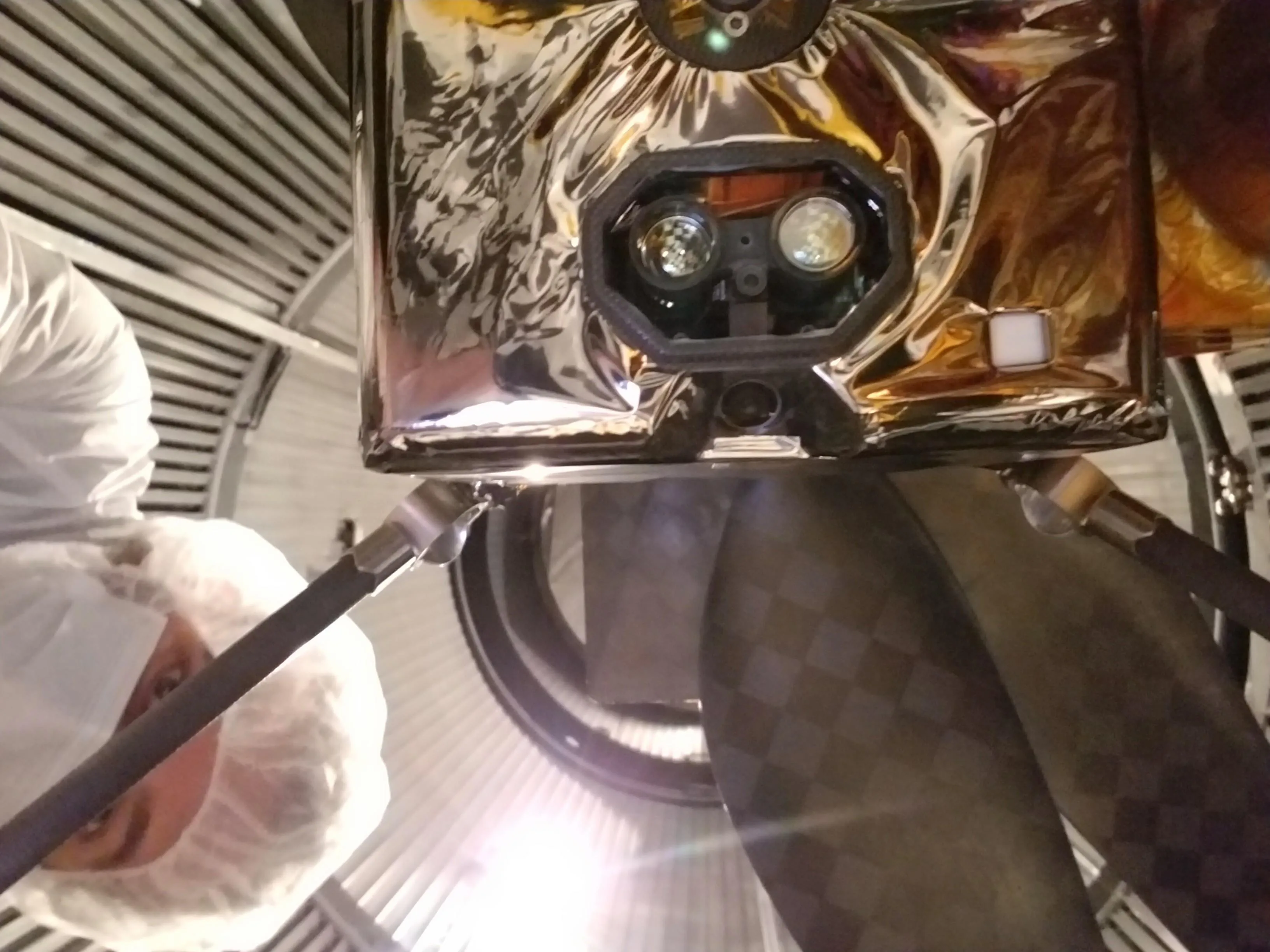
- Planetary aerial systems: Ingenuity offers a concrete example of vision supporting flight navigation. NASA's mission spacecraft description distinguishes its downward navigation camera from its color terrain camera. The featured underside photograph also shows its laser-altimeter optics. It illustrates a purpose-built sensor assembly, not a generic two-sensor recipe.
Test failures as well as nominal accuracy
The following matrix translates the cited estimator, calibration, and interface documentation into proposed integration tests. It is an engineering synthesis, not a published certification procedure or measured test result.
| Test condition | Problem to watch for | Evidence to retain |
|---|---|---|
| Startup using only permitted vehicle motion | Delayed initialization or unstable scale | Startup state, time to usable output, and repeated starts against a known reference |
| Weak texture, blur, or changing illumination | Lost tracks, growing drift, or false confidence | Images, tracking status, pose error, and uncertainty over the affected interval |
| Representative vibration and processor load | Degraded sensing or stale estimates | Raw IMU data, exposure times, output age, and receiving-controller logs |
| Known translations and rotations | Axis signs, frame transforms, or timing disagree | Expected motion alongside transmitted and received pose and velocity |
| Visual loss followed by recovery | Continued invalid output or an unannounced reset | Health transitions, reset counters, recovery time, and controller response |
| A repeated route with loop closure enabled | Map corrections unexpectedly reach local control | Both local and corrected trajectories, frame transforms, and reset handling |
Set mission-specific limits before collecting results: acceptable position and attitude error, maximum estimate age, permitted loss interval, and the required response to degradation. No universal number follows from the term VIO. The route, operating conditions, comparison reference, and failure consequences determine what is useful.
Keep relative motion accuracy separate from whole-route consistency. Report the trajectory-alignment method, whether loop closure was enabled, and the accuracy of the comparison reference. Also record failed runs and initialization failures rather than reporting only successful trajectories. OpenVINS provides an evaluation suite covering trajectory error and estimator consistency, but an integrator still needs tests representative of the intended deployment.
Decide what the mission needs beyond VIO
Select VIO as a local motion-estimation component when the scene and platform motion provide usable observations and the complete integration meets the mission's timing and error needs. Require a working sensor calibration, a defined interface, and demonstrated behavior during loss and recovery before relying on it for control.
For a mission that must return to geographic coordinates or remain aligned with a persistent site map, specify how global corrections enter the system. For obstacle avoidance, specify the separate perception and planning functions. The useful design decision is the full chain from measurement to vehicle response, including what remains available when visual tracking fails.
Sources
- PX4: Visual Inertial Odometry. Official integration overview, applications, and troubleshooting.
- Qin, Li, and Shen: VINS-Mono. Primary research on monocular fusion, initialization, and estimator architecture.
- OpenVINS: IMU Propagation Derivations. Inertial measurement models, biases, and calibration dependencies.
- OpenVINS project documentation. Filter architecture, supported configurations, initialization, and evaluation capabilities.
- VINS-Mono implementation documentation. Loop closure, temporal calibration, rolling-shutter support, and demonstration limits.
- OpenVINS: First-Estimate Jacobian Estimators. Unobservable directions and estimator consistency.
- ROS REP 105: Coordinate Frames for Mobile Platforms. Official source text for odometry and map-frame conventions.
- Kalibr: Camera IMU calibration. Spatial and temporal calibration procedure and timestamp guidance.
- MAVLink common message specification: ODOMETRY. Frames, units, uncertainty, quality, and reset fields.
- PX4: Using Vision or Motion Capture Systems for Position Estimation. External-estimate transforms, fusion configuration, and latency treatment.
- NASA/JPL: Ingenuity mission spacecraft. Historical mission documentation distinguishing the navigation and terrain cameras.
- NASA/JPL: Bottom of Ingenuity Mars Helicopter. Authentic hardware photograph and identification of the camera and altimeter optics.
Last checked: September 7, 2026.