Verification checks whether an autonomous vehicle meets its specified requirements. Validation checks whether those requirements and the resulting vehicle satisfy the intended mission in its actual operating conditions. A vehicle can pass a braking requirement yet remain unsuitable for a route where its sensors detect obstacles too late. Both questions must be answered, with evidence tied to the configuration and conditions being assessed.
Autonomous vehicle testing and validation therefore combine component checks, simulation, hardware integration, controlled physical trials, and operational evaluation. Each exposes different weaknesses. The useful result is a bounded statement about what the system can do, where it can do it, and how it responds when something goes wrong.
On This Page
- Define the system and its operating conditions
- Follow a failure through the vehicle architecture
- Match each question to the right test method
- Turn a scenario into a measurable test
- Understand what standards establish
- Carry the method across air, ground, and maritime systems
- Review the evidence for the intended deployment
Define the system and its operating conditions
The distinction between verification and validation comes from systems engineering. NASA describes verification against design specifications and validation against stakeholder expectations. Testing is only one method: inspection, analysis, and demonstration can also contribute. These activities apply at multiple integration levels, rather than forming a single final exam. NASA's product-realization guidance explains the distinction.
For a hypothetical autonomous delivery vehicle, verification might establish that a stop command reaches the brake controller within the specified time. Validation would ask whether the integrated vehicle can serve the intended delivery route, including crossings, loading areas, obstructions, and recovery from interruptions. An incomplete requirement can be implemented perfectly and still leave the mission unsafe or impractical.
Define the operational design domain, or ODD, before choosing scenarios. For road vehicles, it describes the conditions in which a driving feature is designed to operate. Road geometry, weather, lighting, traffic, and geographic restrictions can all matter. NIST's feature-description report connects the feature, operating conditions, behaviors, and scenarios so that the same capability can be described consistently.
Make those boundaries measurable. “Works in poor visibility” is insufficient: the specification needs an observable visibility condition, the permitted behavior within it, and a response when conditions exceed the supported range. Also state which functions belong to the vehicle, a remote operator, supporting infrastructure, or another system. Otherwise, a successful demonstration may quietly depend on assistance that the proposed operation will not provide.
Follow a failure through the vehicle architecture
A useful functional model follows information from sensing to action:
- Perception turns sensor observations into estimates of objects and surrounding space.
- Localization and state estimation estimate vehicle position, motion, and uncertainty.
- Prediction and planning evaluate possible developments and select a maneuver or trajectory.
- Control and actuation turn that trajectory into steering, braking, thrust, or other physical actions.
- Supervision manages operating modes, degraded operation, and human interaction across that chain.
This is a way to organize tests, not a required software layout. An implementation may combine functions. The important issue is whether a defect can propagate across their interfaces. Research by Fremont and colleagues traced differences between simulated and track behavior and examined failures involving perception, prediction, and planning.
Consider an obstacle estimate that is accurate when produced but arrives late at the planner. Its coordinates alone do not establish that it is usable. Interface checks should cover timestamps, reference frames, units, uncertainty, message age, and validity indicators. NIST's report illustrates why communication delay can affect a vehicle's response; the same timing question belongs wherever information crosses a system boundary.
A hypothetical stop test can distinguish three failures: the vehicle never recognizes the obstacle, it recognizes the obstacle but selects an unsuitable maneuver, or it commands a stop that the actuators cannot deliver in time. Logging only the final collision or stop position loses that distinction. Record enough intermediate state to identify the first failed assumption, then test the correction through the complete chain.
Failure testing also needs to cover functional limitations while hardware remains operational. Glare or an unfamiliar object can challenge intended behavior without a broken component. That distinction is central to ISO 21448:2022, Safety of the Intended Functionality.
Match each question to the right test method
No method sees the entire problem. The following comparison combines NASA's verification methods, NHTSA's test-case and scenario framework, and PX4's hardware-simulation documentation. The allocation advice is editorial synthesis, not a prescribed certification sequence.
| Method | Best suited to answering | Main limitation |
|---|---|---|
| Inspection, analysis, and component tests | Are requirements implemented consistently, and do individual functions meet them? | Correct parts do not establish correct integrated behavior. |
| Software-in-the-loop simulation | How does the software react across many repeatable scenario variations? | Results depend on the simulated environment, sensors, and vehicle dynamics. |
| Hardware-in-the-loop testing | Does software behave as expected on its controller with simulated inputs? | Real computing hardware does not make simulated sensors or actuators physically representative. |
| Controlled track or field trials | Does the integrated vehicle reproduce expected behavior with physical sensors and motion? | Facilities constrain the conditions and encounters that can be reproduced. |
| Operational validation | Does the complete system fulfill the intended mission under representative conditions? | Observed success covers the exposure actually encountered, not every possible event. |
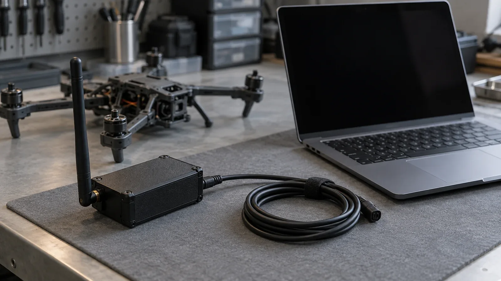
PX4 provides a concrete aircraft example: its hardware simulation executes the flight stack on an actual flight controller while replacing real sensor observations with simulated data. That can expose hardware-integration issues hidden by desktop execution. It does not establish that the aircraft's physical sensors, propulsion, or aerodynamics match the model.
Simulation offers repeatability and broad scenario variation, while physical trials supply checks on real behavior. These benefits create a resource tradeoff: use inexpensive repetition to locate sensitive conditions, then spend physical-test effort on important boundaries and mismatches. A visually realistic scene is not sufficient proof that the variables controlling a particular decision are accurate.
Formal methods can express a safety condition mathematically. Falsification searches for executions that violate it; a finite search without a counterexample is not a proof covering all modeled behavior. Even a proof depends on its assumptions. Fremont and colleagues used formal specifications to select physical tests, with measured differences between simulation and track outcomes.
Turn a scenario into a measurable test
A scenario describes how a situation develops; a test also needs a defined configuration, inputs, measurements, and pass criteria. ASAM's OpenSCENARIO XML describes dynamic simulation content, including coordinated vehicle and pedestrian maneuvers. It helps exchange scenario descriptions. A shared file format does not by itself establish equivalent simulator behavior or an appropriate safety criterion.
For an illustrative pedestrian-crossing case, specify the vehicle's initial speed and position, the pedestrian target's trajectory, the obstruction that limits visibility, the road surface, and the timing of the crossing. Vary those parameters around the conditions that change the vehicle's decision. Set the pass criteria before execution; selecting a forgiving measure after seeing a failure changes the question the test answers. Keep the software build, sensor configuration, map, simulator version, and random seed identifiable so an unexpected result can be reproduced.
Measure more than collision occurrence. For this example, useful outputs include the time of first usable detection, time of the maneuver decision, brake-command timing, physical deceleration, and clearance between the vehicle and target. Define clearance using their geometry: distance between object centers can remain positive during contact. The simulation-to-track study explicitly encountered that measurement distinction.
An illustrative timing calculation shows why interface latency matters. At an assumed constant speed of 10 metres per second, an additional 0.2-second delay consumes 2 metres before any subsequent braking response:
Additional distance = speed × added delay = 10 m/s × 0.2 s = 2 m.
This is an arithmetic example, not a measured vehicle result or a safe stopping-distance specification. Braking capability, road friction, slope, detection uncertainty, and the target's motion still need separate treatment.
Keep scenario coverage separate from operational frequency. A deliberately difficult test set can reveal weaknesses without representing how often those encounters occur on a route. Conversely, many uneventful miles can miss a rare consequential event. RAND's 2016 statistical study showed why injury and fatality rates are difficult to establish through road mileage alone. Its numerical estimates used stated assumptions; they are not a universal mileage requirement.
For a deployment decision, ask both whether difficult cases have been challenged and whether the evidence represents the intended operating conditions. Neither a raw pass percentage nor a mileage total answers both questions.
Understand what standards establish
Two road-vehicle standards address different parts of this work:
- ISO 21448:2022 provides a framework and guidance for safety of the intended functionality, including risks arising from functional insufficiencies. Its public scope distinguishes those concerns from faults covered by the ISO 26262 series.
- ISO 34502:2022 describes a scenario-based safety-evaluation framework for automated driving systems on limited-access highways. Its public scope excludes cybersecurity, human-machine-interface issues, and non-safety topics such as comfort and energy efficiency. See the ISO 34502 scope.
These are standards with defined scopes. Referencing either does not establish that a vehicle is certified, approved for a particular operation, or compliant with every applicable requirement. Nor should the limited-access-highway scope be silently extended to a warehouse robot, aircraft, or vessel. A supplier's standards claim should identify the edition, covered function, evaluated configuration, and supporting assessment.
Carry the method across air, ground, and maritime systems
The general questions transfer across vehicle classes; the operating conditions and success criteria change. The following are illustrative applications, not test results or universal operating procedures.
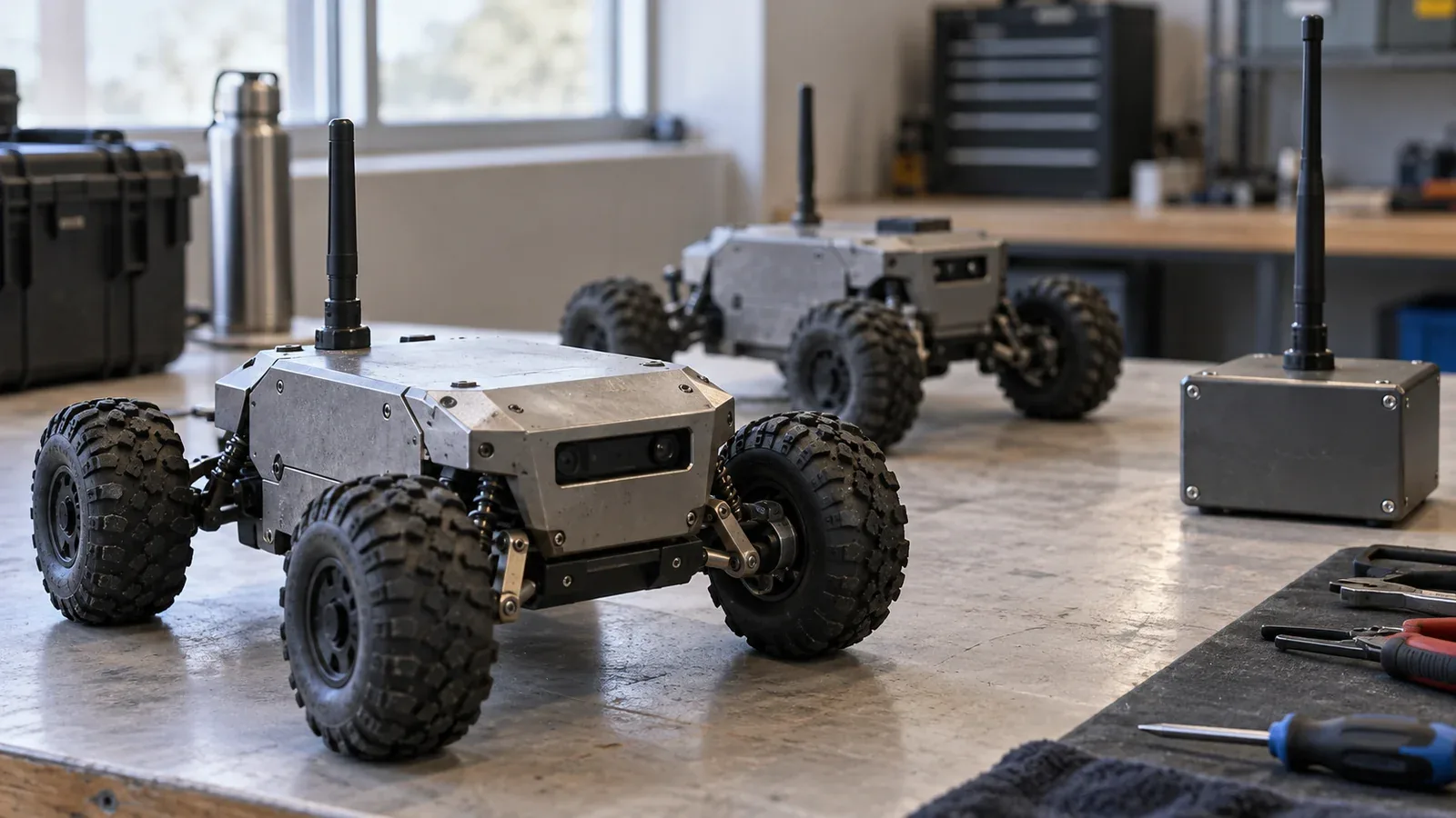
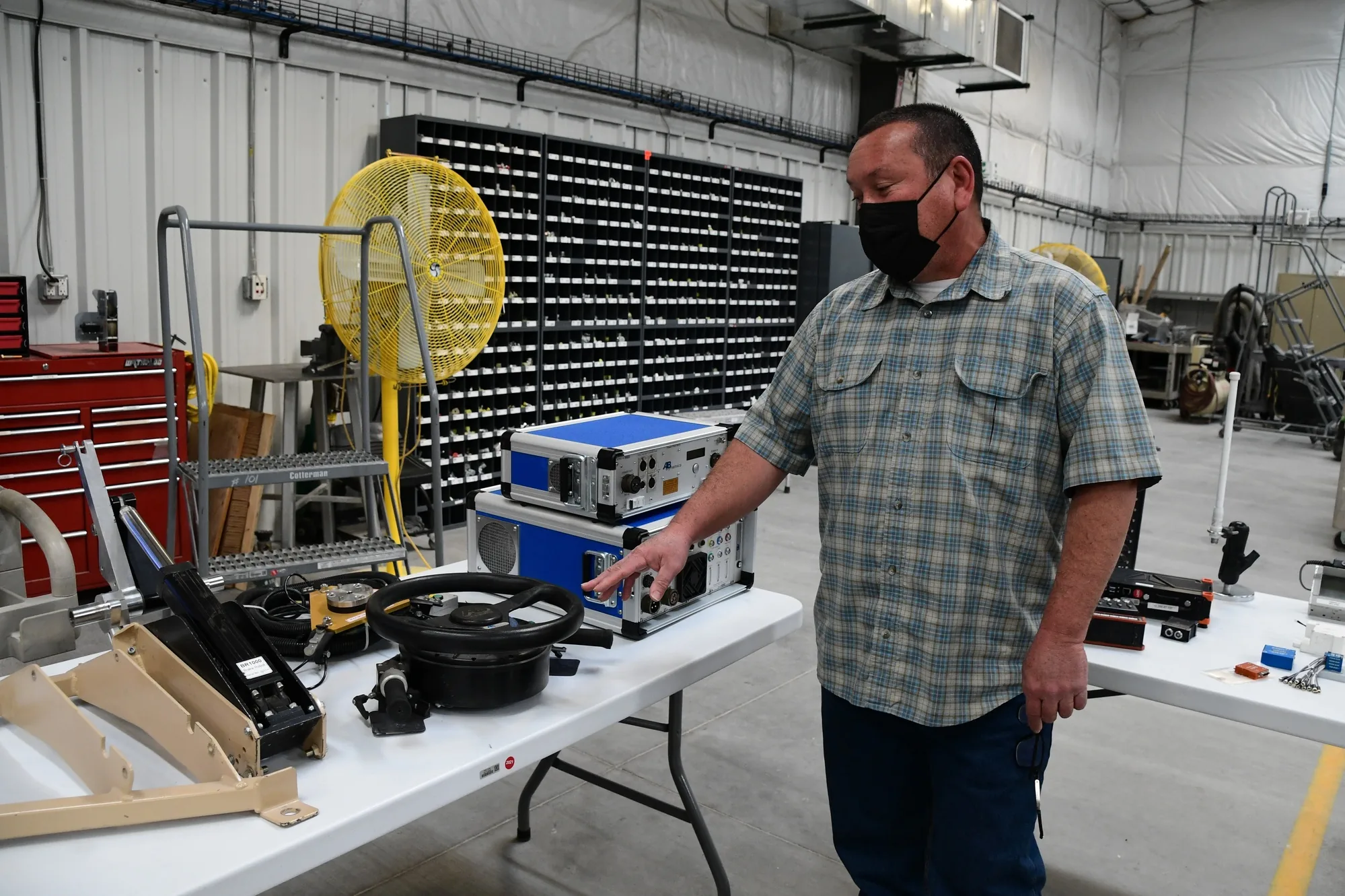
For an autonomous ground vehicle, repeatable control of other actors can make avoidance tests more informative. The U.S. Army's Yuma Proving Ground account describes robotic vehicle controls and moving soft targets used to support repeatable scenarios. A test robot that drives a target vehicle is part of the test apparatus; it should not be confused with the autonomous system being evaluated.
For an unmanned aircraft, hardware simulation can examine controller behavior before flight. A mission-specific validation case could then ask whether navigation degradation is detected and whether the selected contingency remains compatible with terrain, energy, and the operating area. A commanded return is not a successful outcome if the assumed navigation capability is unavailable.
For an autonomous surface vessel, a proposed validation case might combine a crossing encounter with environmental disturbance and interrupted communications. Define whether onboard autonomy or a remote operator must resolve the encounter, then measure that complete response. A stationary stop should not be assumed to be a suitable fallback for every vehicle or environment.
These examples apply the system-boundary and mission-validation principles in NASA's guidance. Domain-specific operational rules and assurance requirements still need their own treatment.
Review the evidence for the intended deployment
A useful supplier review starts with the mission and traces a small number of consequential behaviors all the way to recorded results. NASA's verification and validation plan outline calls for responsibilities, methods, integration activities, and supporting documentation. Applied to an autonomous-vehicle purchase or program review, request:
- The supported operating conditions and who performs each driving, supervisory, and recovery function.
- Requirements linked to hazards, tests, measured outcomes, and unresolved deviations.
- The tested hardware, software, learned-model, calibration, and map versions.
- The basis for simulator credibility, including important disagreements with physical trials.
- Evidence for degraded operation, mode changes, and recovery, alongside normal mission success.
- A change-impact assessment explaining which evidence remains applicable after an update and which tests must be repeated.
Evaluate safety and usefulness together without allowing one to erase the other. A vehicle that repeatedly stops unnecessarily may be conservative in an individual encounter yet fail its intended service. Faster progress is not an adequate answer if it reduces the margin needed to handle uncertainty.
The deployment question is whether the evidence supports this configuration performing this mission within these operating limits. Where that chain breaks, the next step is specific: improve a requirement, correct an interface, investigate a model mismatch, add a missing scenario, or narrow the proposed operation.
Sources
- NASA Systems Engineering Handbook, Product Realization: systems-engineering guidance distinguishing verification, validation, integration, and their methods.
- NIST IR 8534, Feature Description for Assessing Autonomous Vehicle Performance, September 2024: government technical report connecting operating conditions, features, behaviors, scenarios, and performance descriptions.
- Fremont et al., Formal Scenario-Based Testing of Autonomous Vehicles: From Simulation to the Real World, 2020: original research on simulation-guided track testing and differences between simulated and physical results.
- NHTSA, A Framework for Automated Driving System Testable Cases and Scenarios, 2018: government research framework covering scenarios and test methods; not a vehicle approval.
- PX4, Hardware Simulation: implementation-specific documentation explaining execution on real flight-controller hardware with simulated inputs.
- ASAM OpenSCENARIO XML: standards-body description of the format's dynamic-scenario scope.
- RAND, Driving to Safety, 2016: original statistical research on limitations of mileage-only safety demonstrations.
- ISO 21448:2022: official public scope of the safety-of-the-intended-functionality standard; full requirements are not reproduced here.
- ISO 34502:2022: official public scope and exclusions of the scenario-based evaluation framework.
- U.S. Army Yuma Proving Ground, autonomous vehicle testing, March 22, 2022: official account of robotic controls and repeatable target maneuvers.
- NASA Systems Engineering Handbook, Appendix: suggested verification and validation plan content and responsibilities.
Last checked: September 8, 2026.