Autonomous vehicle path planning searches for a collision-free sequence of positions and orientations under a model of the vehicle and its surroundings. A* and Dijkstra search connected states; Hybrid A* and state lattices represent feasible maneuvers; sampling methods such as RRT explore continuous spaces; trajectory optimization adds motion constraints and timing. The right choice depends on the vehicle, environment, and available computation.
A path alone does not tell a vehicle when to accelerate, yield, or brake. Practical autonomy connects path generation to prediction, trajectory generation, feedback control, and a defined response when no usable plan is available.
On This Page
- Where planning fits in the vehicle
- How the main algorithms work
- What makes a path executable
- Interfaces that need an explicit agreement
- Failure modes and performance tradeoffs
- Match the planner to the application
Where planning fits in the vehicle
Distinguish three outputs. A route identifies the broad connection to the destination, such as a sequence of road segments. A path specifies positions and, where needed, orientations along that route. A trajectory adds how motion evolves over time, including speed. Feedback control translates the reference into steering, propulsion, and braking actions while correcting tracking error.
For road vehicles, a behavior layer also chooses actions such as staying in lane, yielding, or changing lanes. Perception and localization supply estimates of the surroundings and vehicle state. Prediction describes possible future motion of other road users. The planning and control survey by Paden and colleagues explains this hierarchy and the importance of matching the motion model to the task.
Consider an illustrative warehouse tug approaching a blocked aisle. Its route selects another aisle; its path includes the turn needed to reach it; its trajectory slows for that turn and accounts for a crossing worker. Its controller then attempts to execute the motion. Success at the route level does not establish that the tug can make the turn or pass the worker safely.
How the main algorithms work
Dijkstra and A*: search a graph
Dijkstra expands states in order of accumulated cost. A* adds an estimate of the remaining cost to focus the search toward the goal. A graph can represent road connections or neighboring cells in an occupancy grid. An occupancy grid divides space into cells marked or estimated as occupied, free, or unknown.
For a finite graph with nonnegative edge costs, Dijkstra finds a least-cost route. A* uses accumulated cost plus a heuristic estimate. An admissible heuristic never overestimates remaining cost; graph-search implementations must also handle revisited states correctly, or use the stronger consistency condition. Those guarantees concern the graph and chosen cost, not every physically possible trajectory. LaValle's discrete-planning chapter develops these search methods.
D* Lite: reuse previous search work
When a rover discovers a blocked passage, rebuilding every search result can waste useful work. Koenig and Likhachev's D* Lite research describes incremental heuristic search that reuses information across related planning problems. It is relevant to navigation while terrain information changes.
Replanning after an obstacle update and predicting a moving obstacle are separate capabilities. Updating a blocked grid cell does not specify when a person will leave that cell. A system using D* Lite still needs an appropriate representation of motion and time for such encounters.
Hybrid A* and state lattices: search feasible maneuvers
A car cannot move sideways into the next free cell. Hybrid A* incorporates vehicle heading and motion-based expansions. A state lattice connects states using a predefined set of feasible motion segments, often called motion primitives.
Nav2's Smac planner documentation provides a concrete implementation distinction: its 2D planner serves circular or omnidirectional robots, Hybrid A* supports car-like motion, and its lattice planner supports configurable robot kinematics. The latter two support reversing. Whether the vehicle should reverse remains an application decision.
RRT, RRT*, and PRM: sample the search space
A rapidly exploring random tree, or RRT, grows connections toward sampled states. A probabilistic roadmap, or PRM, builds a network of sampled collision-free connections that can support subsequent queries. Sampling avoids explicitly enumerating a fine grid across every state dimension, but narrow passages can be difficult to discover. See LaValle's sampling-based planning chapter.
RRT* improves connections as the search progresses. Karaman and Frazzoli's original analysis establishes asymptotic optimality for RRT* and PRM* under its mathematical assumptions: solution cost approaches the optimum as sampling continues. This does not promise an optimal answer before a vehicle's next planning deadline. Probabilistic completeness likewise describes limiting behavior, not a guaranteed finite response time.
Trajectory optimization and model predictive control
Trajectory optimization adjusts a sequence of states and controls to minimize a cost while satisfying constraints. These may include vehicle dynamics, collision clearance, and actuator limits. Obstacle avoidance can make the problem nonconvex, meaning a solver can converge to a locally good solution without finding the best route around every obstacle.
Model predictive control, or MPC, repeatedly estimates the current state, optimizes over a future horizon, applies the first control action, and solves again. Russ Tedrake's MIT trajectory-optimization notes explain this relationship. MPC may handle local motion generation or track an upstream reference, depending on the architecture; it does not automatically replace route planning.
The following comparison combines those algorithm descriptions. Application fit is engineering interpretation, not a benchmark ranking.
| Method | Useful starting point | Main qualification |
|---|---|---|
| Dijkstra or A* | Road graphs and modest-dimensional grid searches | Graph connectivity and cost determine the answer |
| D* Lite | Repeated searches as map costs change | Map repair alone does not predict obstacle motion |
| Hybrid A* or state lattice | Car-like turns, parking, and maneuvering | Vehicle model and available motion segments constrain solutions |
| RRT or PRM | Continuous spaces with several state dimensions | Sampling and connection checks must capture useful passages |
| RRT* or PRM* | Improving path cost as computation permits | Asymptotic results do not establish deadline performance |
| Trajectory optimization or MPC | Timing, smoothness, and constrained local motion | Solver behavior, initialization, and model accuracy matter |
What makes a path executable
Represent the vehicle footprint, not just its center. A centerline can clear a corner while a bumper or payload strikes it. Check intermediate motion between stored waypoints as well as the waypoints themselves. Adding smoothing must not invalidate the collision checks that accepted the original path.
Also distinguish kinematic feasibility from dynamic feasibility. A geometric turn may satisfy a steering limit but demand excessive acceleration at the chosen speed. LaValle's vehicle-model chapter distinguishes movement constraints and dynamical models. A speed profile and controller must agree with whichever assumptions the planner uses.
The optimization objective needs the same scrutiny. In the Open Motion Planning Library, the documented geometric RRT* example defaults to path length unless another objective is supplied. Its optimal-planning tutorial also separates the optimization objective from state-validity checking. Consequently, “optimal” is incomplete without identifying both the cost and the admissible motions.
For a delivery robot, a slightly longer route might be preferable if it avoids a difficult doorway. For a survey vehicle, path length alone may overlook the energy needed to oppose a disturbance. These are illustrative objective-design choices, not measured advantages of a particular algorithm. Encode the actual task before comparing results.
Interfaces that need an explicit agreement
A planning component needs more than a start and goal. Agree on coordinate frames, units, timestamps, vehicle reference point, obstacle representation, and the meaning of unavailable data. A pose referenced to the rear axle cannot be silently treated as the center of the body.
Autoware's trajectory-ranker documentation gives a concrete software example. Inputs include candidate trajectories, predicted objects, odometry, a map, and a route. It evaluates multiple criteria, including trajectory deviation and motion-related metrics. A richer input contract lets downstream selection evaluate more than shortest distance.
For integration, document these four agreements:
- State and map: how old each input may be, how coordinate transforms are resolved, and how uncertain or unknown space is treated.
- Vehicle model: footprint, allowed direction changes, steering behavior, acceleration limits, and the conditions under which that model is credible.
- Planner output: path versus timed trajectory, reference point, speed semantics, valid horizon, and explicit failure or timeout status.
- Execution response: which component rejects unusable motion, how long an earlier trajectory remains usable, and what behavior follows a rejected update.
These are integration recommendations. Specific field names and responsibilities vary by software stack. Reusing the previous trajectory should require checking that it remains appropriate for the current scene, rather than treating its earlier acceptance as permanent.
Failure modes and performance tradeoffs
A planner can produce an answer quickly and still produce unusable motion. Autoware's planning-validator documentation describes checks for trajectory age, shape, and selected collision situations before passing a trajectory to control. Its configured handling of invalid output is part of system behavior, not a universal safety guarantee.
The table below applies the cited search, optimization, and software-interface principles to diagnosis. Symptoms can have multiple causes; the proposed checks are engineering interpretation.
| Observed problem | Possible cause | What to inspect |
|---|---|---|
| A free-looking corridor has no solution | Footprint, map resolution, or motion constraints exclude it | Compare actual geometry with represented free space and permitted turns |
| A path is found but cannot be tracked | Planner and controller assume different motion limits | Replay the reference with the configured vehicle model and speed profile |
| The robot alternates around an obstacle | Small scene changes favor different candidates | Compare successive inputs, candidate costs, and commitment behavior |
| Average runtime is acceptable but updates arrive late | Difficult scenes or collision checking create a long runtime tail | Measure deadline misses and input-to-command age under load |
| A moving obstacle conflicts with an accepted path | Prediction or time alignment is missing or stale | Inspect predicted occupancy at the intended arrival times |
| A smoother path clips a corner | Postprocessing changed previously checked geometry | Repeat footprint and intermediate-motion checks after smoothing |
For an evaluation, hold the map, footprint, start and goal, constraints, compute platform, and time budget constant. Record time to first feasible solution separately from time spent improving it. For randomized planners, repeat runs with documented seeds and report the distribution, including failures.
Then evaluate the whole navigation loop. Measure tracking error, minimum clearance under the stated measurement method, acceleration demands, stale-input behavior, and recovery from an unavailable route. Set task-specific limits before comparing planners. A short average search time cannot compensate for frequent deadline misses in the scenes the vehicle must handle.
Match the planner to the application
For a warehouse mobile robot, start with floor geometry and drive type. A circular robot that can turn in place presents a different search problem from a tug pulling a load through tight corners. Nav2's documented planner distinctions provide useful starting points, but a towing configuration needs its own applicable model.
For parking and yard maneuvering, explicitly represent heading, turning constraints, and whether reversing is permitted. For road driving, route and maneuver selection must connect to timed interaction with other road users. A static free-space planner alone does not resolve a merge.
For an aerial inspection or underwater survey concept, first identify which dimensions and disturbances materially constrain motion. A three-dimensional geometric route is only one input to a feasible flight or swimming trajectory. Applying a ground-robot implementation without reviewing those assumptions would leave essential parts of the problem unspecified.
Choose a candidate algorithm only after defining the motion it must produce and the deadline it must meet. Demonstrate that output with the intended controller, map representation, and difficult operating scenarios. The useful result is a vehicle that can execute the plan and respond coherently when the next plan is unavailable.
Sources
-
Paden et al., A Survey of Motion Planning and Control Techniques for Self-driving Urban Vehicles: research survey of planning hierarchy, vehicle models, and control.
-
LaValle, Planning Algorithms, Chapter 2: author-hosted technical text on discrete search and optimal planning.
-
Koenig and Likhachev, D* Lite: original 2002 research record on incremental heuristic replanning.
-
Nav2, Smac Planner: Rolling documentation for 2D, Hybrid A*, and state-lattice implementations.
-
LaValle, Planning Algorithms, Chapter 5: author-hosted technical text on sampling, roadmaps, and collision checking.
-
Karaman and Frazzoli, Sampling-based Algorithms for Optimal Motion Planning: original analysis of RRT* and PRM* guarantees.
-
Tedrake, Underactuated Robotics: Trajectory Optimization: author-maintained MIT notes on constrained optimization and MPC.
-
LaValle, Planning Algorithms, Chapter 13: author-hosted technical text on differential vehicle models.
-
OMPL, Optimal Planning Tutorial: developer documentation separating validity checks and optimization objectives.
-
Autoware, Trajectory Ranker: development documentation for candidate evaluation and input interfaces.
-
Autoware, Planning Validator: development documentation for trajectory checking and configurable invalid-output handling.
-
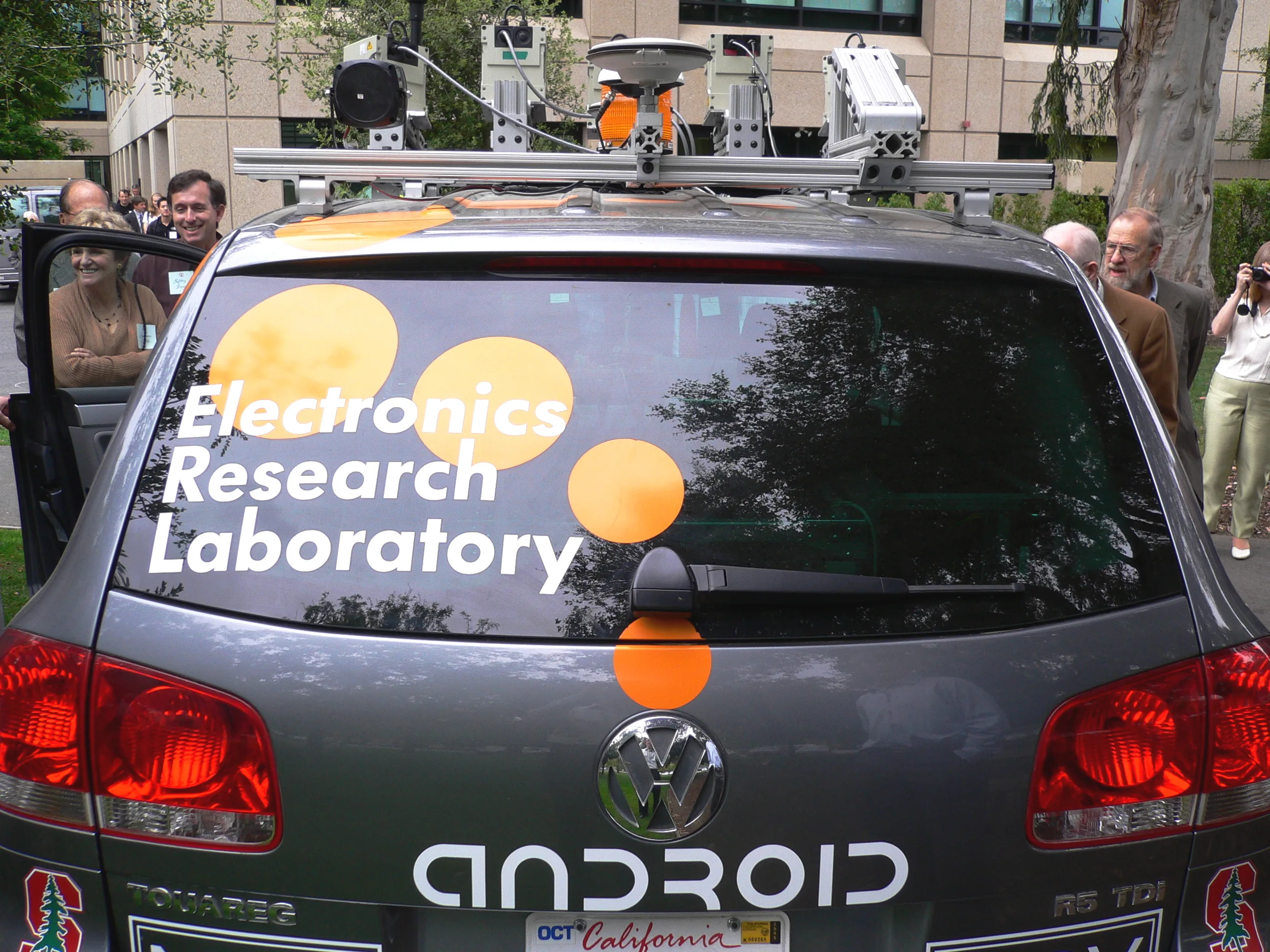
Featured photograph: Steve Jurvetson, R2D2 goes 4WD, May 2005, via Wikimedia Commons. Reused unmodified under Creative Commons Attribution 2.0.
Last checked: September 8, 2026.