USBL, LBL, and SBL locate underwater targets using sound, but place their reference sensors differently. USBL concentrates an array in one compact head, LBL spreads reference transponders around a work area, and SBL separates sensors across a vessel or structure. Choose among them by the reference geometry your mission can support, the position uncertainty it can tolerate, and the installation work it can sustain.
For mobile tracking, USBL is usually the starting point. For repeated precision work within a defined subsea site, evaluate LBL. SBL merits consideration when a platform can accommodate a surveyed, distributed array. These are architecture choices, not accuracy grades: the complete installation and operating geometry determine the result.
On This Page
- Compare the reference geometry
- How each system obtains a position
- What an accuracy specification leaves out
- Integration from transponder to navigation system
- Acoustic limitations and lost fixes
- Choose for the mission and verify the installation
Compare the reference geometry
The baseline is the separation between reference elements. The table compares conventional arrangements; inverted and hybrid systems can place components differently.
| Decision point | USBL: ultra-short baseline | LBL: long baseline | SBL: short baseline |
|---|---|---|---|
| Reference arrangement | Closely spaced hydrophones in one head | Widely separated reference transponders, commonly on the seabed | Separate transducers distributed across the vessel |
| Main acoustic measurements | Range and arrival direction | Ranges to known reference positions | Arrival-time or range differences across the array |
| Initial coordinate reference | Acoustic head | Surveyed array | Vessel array |
| Installation burden | Head mounting and sensor alignment | Deploy, survey, maintain, and recover references | Multiple mounts, cables, and accurately measured baselines |
| Geometry to examine | Slant range and target direction | Target position relative to usable references | Available baseline relative to target distance |
| Mission to evaluate first | Tracking while moving between sites | Repeated work within a defined subsea area | Vessel-based work with room for a permanent array |
Architecture basis: IHO Manual on Hydrography, Chapter 2, section 6.3 and EvoLogics positioning documentation, checked September 7, 2026. Mission fit is editorial interpretation of the installation tradeoffs. The IHO manual supplies foundational principles, not current product performance limits.
How each system obtains a position
USBL measures distance and direction from one head
A transponder replies to an acoustic interrogation. Travel time, after accounting for the transponder's reply delay, provides slant range: the direct distance between head and target. Phase differences across the head's hydrophones provide arrival direction.
Geographic coordinates also require the head's position, heading, and attitude. A surface global navigation satellite system (GNSS) supplies the geographic reference. Tritech's USBL explanation describes this measurement chain. USBL is also called super-short baseline, or SSBL; SSBL and SBL are different terms.
LBL solves ranges against a surveyed array
The vehicle or positioning unit exchanges signals with multiple references whose coordinates are known. The solver finds a position consistent with those distances, a process called multilateration. Array calibration establishes the relationships between references; geographic referencing ties that local geometry to a datum.
This separates two questions: how consistently the vehicle can return to a location within the array, and how accurately that location is placed on a geographic map. A tight local solution can still inherit an error in the array's geographic reference. The IHO's LBL treatment distinguishes relative geometry, orientation, and absolute positioning.
SBL uses the platform as the baseline
SBL distributes receivers instead of packaging them in one head. Its measured baselines, receiver timing, and motion corrections become installation responsibilities. Increasing useful separation can improve the geometry, but a wider array is valuable only if its positions are known accurately and remain stable.
EvoLogics describes SBL as a vessel installation requiring precise calibration and motion compensation. For an operator changing charter vessels frequently, that installation burden may outweigh its benefits. For a dedicated platform, it can be evaluated over the planned service life.
What an accuracy specification leaves out
Slant range is not water depth. A target far to the side can be much farther from the transceiver than its depth suggests. Angular uncertainty converts into a larger position error as the distance increases. Research on USBL array geometry and error propagation also shows why phase, sound-speed, and array-spacing errors cannot be ignored. Its simulations describe the studied model, not every commercial system.
As an illustrative geometric calculation, assume a 0.1-degree direction error and a 1,000-metre slant range. The transverse displacement is approximately range multiplied by angular error in radians:
1,000 m × (0.1 × π / 180) ≈ 1.75 m.
At 3,000 metres, the same angular error gives approximately 5.24 metres. These are rounded calculations for a hypothetical angle error, not measured system accuracy. They omit range error, geographic-reference error, water-column effects, and other installation errors.
For LBL, inspect the array layout and the ranges actually available along the route. Widely separated references do not help a vehicle that cannot hear them. A cluster of usable references in one direction constrains movement less evenly than a well-distributed set. Sonardyne's comparison of positioning methods emphasizes array planning and redundant ranges for detecting bad observations. Distinguish the observations needed to solve a position from the extra observations needed to identify an erroneous measurement.
Before comparing supplier numbers, request the same output definition: horizontal or three-dimensional error, confidence level, absolute accuracy or repeatability, real-time or processed result, and the included supporting sensors. Also request the tested target geometry. An acoustic range precision figure alone cannot establish the uncertainty of a georeferenced vehicle position.
Integration from transponder to navigation system
A useful integration review follows the measurements through to the system that needs them.
Mounts and offsets: Measure the distances between the acoustic head, GNSS antenna, motion sensor, and required reporting point. Those offsets are often called lever arms. Establish axis conventions and alignment corrections. Sonardyne's Ranger 2 calibration guidance calls out sensor quality, offsets, current sound-speed profiles, stable calibration beacons, and a verification run after calibration.
Position delivery: Establish where the fix is computed and who receives it. A shipboard display showing an autonomous underwater vehicle (AUV) does not establish that its onboard controller receives those positions. EvoLogics distinguishes remote positioning from onboard self-positioning; a remotely computed fix needs a communication path back to the vehicle if it is to aid navigation.
Interface questions: Request message definitions covering coordinate frame, units, timestamps, fix validity, and uncertainty. Confirm whether the reported point is the transponder or a corrected vehicle reference point. A practical integration demonstration should show how the receiver handles delayed, invalid, and missing observations, not merely that coordinates appear on a screen.
Hybrid navigation: An inertial navigation system (INS) propagates motion between acoustic observations. Sparse LBL uses fewer acoustic references together with inertial aiding; it is not equivalent to a full acoustic array with some beacons removed. Sonardyne's sparse-LBL description identifies both the required INS and the reduction in acoustic redundancy. Ask how the solution behaves when the remaining reference is unavailable.
Acoustic limitations and lost fixes
All three architectures need usable acoustic paths. Machinery, other sounders, and delayed reflections can interfere with measurements. Tritech's practical guidance connects reliable USBL operation to mounting and the acoustic environment.
Propagation imposes delay. At an illustrative 1,500 m/s, a 1,000-metre out-and-back exchange takes 2 × 1,000 / 1,500 ≈ 1.33 seconds, excluding reply and processing delays. Scheduling and retransmissions add time; electrically triggered responders use a different timing path. Specify usable observation age separately from the navigation system's output frequency.
Sound-speed variation bends acoustic paths. For USBL targets well away from directly beneath the head, pressure-derived depth can improve the solution where acoustically derived depth becomes weak. Sonardyne's depth-aiding guidance explains this geometry and the effect of refraction. Adding a depth sensor does not correct an erroneous heading or an incorrect geographic reference.
For a trial, distinguish a rejected fix, a plausible biased fix, and a navigation estimate continuing without fresh acoustics. Request results with representative vessel machinery and other acoustic equipment operating. For LBL, include loss of a reference and the edge of the intended work area; for vessel arrays, include representative heading and target direction changes. These tests reveal different weaknesses.
Turn a suspicious track into a specific test
The following checks are engineering interpretations of the measurement chain, not diagnoses that can be made from a plot alone. Compare the acoustic observations with an independently established reference before changing calibration values.
| Observation during a controlled trial | Question to investigate | Useful comparison |
|---|---|---|
| A fixed target appears to move when the vessel changes heading | Are heading, array alignment, offsets, and sensor times consistent? | Repeat observations of the same reference on different headings while retaining raw measurements |
| A repeatable local LBL track is displaced on the geographic map | Is the array correctly tied to the project's coordinate reference? | Compare local array residuals separately from independently surveyed geographic control |
| A solution becomes unstable only near one edge of the work area | Which references remain audible, and what geometry do they provide? | Plot accepted ranges and their reference locations alongside the route |
| A smooth navigation track continues after acoustic fixes stop | Is the displayed position propagated by an inertial estimator? | Check the age of the last accepted acoustic observation and the reported uncertainty |
Diagnostic basis: the calibration, LBL, and computation-location documentation cited above. A similar-looking track can have several causes; the purpose is to isolate an input or reference relationship for testing.
Choose for the mission and verify the installation
For a short inspection campaign moving between locations, evaluate USBL first and budget for mounting, calibration, and acoustic checks. For repeated mapping or intervention around a fixed subsea site, evaluate whether LBL's stable local reference justifies deployment and recovery work. For a dedicated vessel with space and a long operating horizon, compare a properly surveyed SBL installation against a compact USBL head using the same mission requirements.
Consider two hypothetical assignments with the same vehicle. In the first, the operator needs to relocate widely separated inspection targets during a brief campaign. A proposal should explain how each new location is reached and referenced without repeated array installation. In the second, the vehicle must revisit a small work area across several deployments. The proposal should explain how the local reference is preserved and checked between visits. The vehicle has not changed, but the value of a reusable LBL array has.
Likewise, evaluate SBL against the actual host platform. Ask who surveys the receiver positions after installation, how mounting changes are recorded, and whether a move to another vessel requires a new calibration. For USBL, ask which sensors and alignment steps are included when the head is supplied. Comparing only the acoustic hardware leaves these responsibilities unresolved.
Before selecting any architecture, write down the required position reference, permitted uncertainty, operating area, and maximum usable observation age. Ask the supplier to demonstrate those conditions with the proposed sensors and installation. The deciding evidence is whether the complete system can locate the required point throughout the mission, including the conditions in which it must report that the position is no longer reliable.
Sources
- IHO, Manual on Hydrography, Chapter 2: institutional technical manual, with corrections through February 2011; section 6.3 explains baseline arrangements and reference geometry.
- EvoLogics, Underwater Positioning: manufacturer documentation on architecture, SBL installation, and onboard versus remote computation.
- Tritech, How does a USBL system work?: manufacturer FAQ on ranging, direction measurement, georeferencing, and acoustic interference.
- An Ultra-Short Baseline Positioning Model Based on Rotating Array & Reusing Elements and Its Error Analysis: 2019 research paper examining array errors through analysis and simulation.
- Sonardyne, Pros and cons of positioning methods: manufacturer explanation of LBL, USBL, sparse LBL, and acoustic redundancy.
- Sonardyne, Calibration tips for Ranger 2: implementation guidance on reference sensors, offsets, environmental inputs, and verification.
- Sonardyne, When to use depth aiding: technical guidance on target geometry, refraction, and pressure-derived depth.
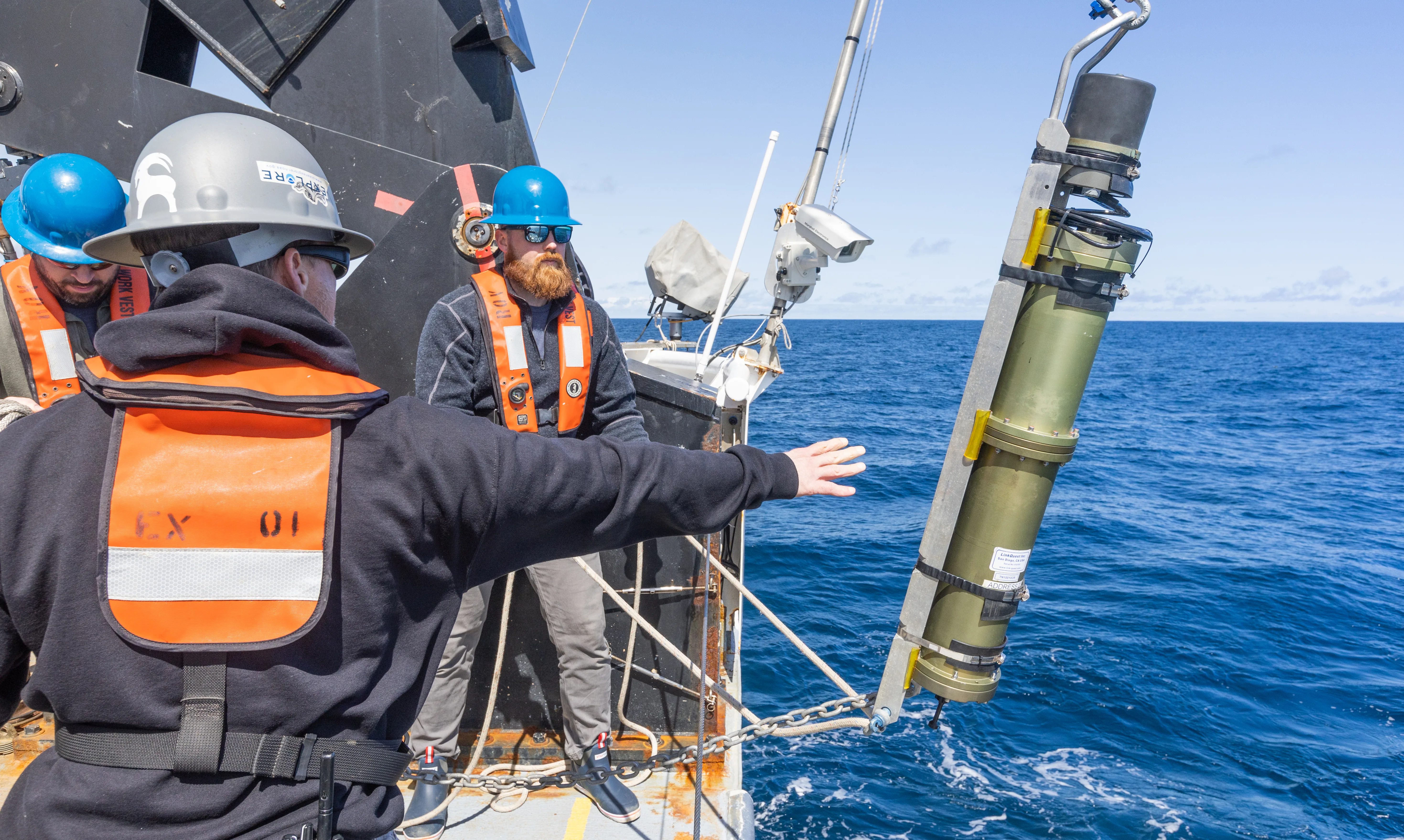
- NOAA Ocean Exploration, Preparing the USBL: original context and credit for the featured 2023 calibration photograph.
Last checked: September 7, 2026.