An ROV tether management system (TMS) stores, pays out, and retrieves the cable between a remotely operated vehicle and a subsea deployment unit. It lets the vehicle work on a local tether while the surface umbilical connects the deployment unit to the vessel. The purpose is to reduce the effect of vessel motion on the working vehicle and manage its excursion from the deployment point. FET's TMS overview describes this arrangement.
The engineering question is whether the complete system can deploy, support, and recover the ROV through its intended mission. Drum capacity alone cannot answer that question: the cable path, load-bearing connections, controls, and return route all matter.
On This Page
- Where the TMS sits in the system
- Top-hat, garage, and direct deployment
- How payout, power, and controls interact
- Why stored length is not usable excursion
- Failure modes to review before mobilization
- Specify the complete out-and-back mission
Where the TMS sits in the system
In a typical two-stage arrangement, the surface winch handles the main umbilical; the subsea TMS handles the vehicle's working tether. The main umbilical and its termination form part of the deployment load path. The softer vehicle tether carries services to the ROV while allowing local movement. Power and data arrangements depend on the particular system.
WHOI's Jason/Medea system illustrates the separation clearly. An armored cable connects the ship to Medea, and a neutrally buoyant tether connects Medea to Jason. The intermediate body supports tether management and carries cameras. This scientific two-body configuration illustrates the principle without being interchangeable with a commercial drum-based TMS. NDSF's Jason capabilities also describes a single-body configuration using cable buoyancy and a heave-compensated winch.
Three functions should therefore be specified separately:
- Launch and recovery: moving the assembly through the deck, overboarding, and water-entry stages.
- Tether handling: controlling how much working cable is outside the subsea unit.
- Vehicle control: navigating and doing useful work with the ROV.
A working vehicle does not prove that its recovery equipment or tether controls are ready. Treat their interfaces as part of the system design.
Top-hat, garage, and direct deployment
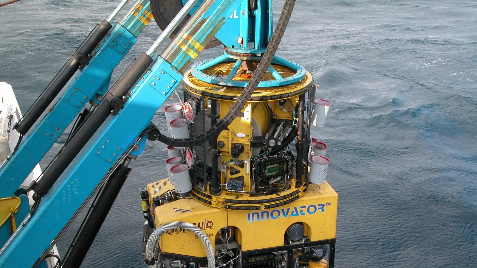
A top-hat TMS sits above the vehicle when docked. A garage arrangement receives the vehicle within a supporting frame. Both provide a subsea departure and return point; the geometry changes how the ROV approaches, latches, and clears its surrounding structure. FET documents both families for observation and work-class systems, including optional propulsion on some models.
The useful comparison is the actual vehicle envelope: manipulators, skids, tools, connectors, and any equipment that changes docking clearance. Request drawings showing the fully equipped ROV, its approach path, and its secured position. A compatible bare frame does not establish clearance after a project tool package is installed.
Saab's Seaeye Tiger documentation distinguishes free-swimming deployment from use with its Type 8 TMS. It also identifies different deployment equipment, including an A-frame launch and recovery system (LARS) for TMS operation. This is a concrete example of why adding a tether manager affects the surface equipment as well as the vehicle. Seaeye Tiger datasheet, revision 4
For a short, accessible inspection, evaluate whether direct deployment satisfies the mission before accepting the additional subsea machinery and docking sequence. Where the vehicle must work away from a deep deployment point, evaluate a TMS against the required excursion and recovery arrangement. Neither layout is universally preferable.
How payout, power, and controls interact
The handling mechanism must put cable back into storage in a controlled pattern. SMD's September 2015 ULX announcement describes a driven sheave arrangement intended to maintain even wraps while reducing reverse bending and twist. It is a design example, not evidence that every system uses the same mechanism. SMD's ULX TMS description
Payout and retrieval also need feedback. FET identifies tether-load sensing and proportional speed control as design features. During integration, establish what the operator can see: line out, handling speed, tension where measured, docking state, and relevant alarms. Specify the response to a missing or implausible signal rather than assuming that every installation handles it identically.
Too little working cable can constrain the vehicle; uncontrolled slack can create a fouling problem. In an out-and-back operation, payout follows the vehicle's departure, retrieval manages the returning cable, and docking secures the vehicle for recovery. The permitted tensions, speeds, and sequencing must come from the selected system's instructions. Automatic payout addresses only part of that task. It does not by itself establish obstacle avoidance or autonomous recovery. The distinction between autonomous and automated systems helps separate these responsibilities.
For electrical and data integration, trace the service path from the surface supply through the umbilical, subsea connections, and vehicle tether. Saab's Tiger sheet documents optical multiplexing with video, serial-data, and Ethernet interfaces. These labels identify services; they do not establish compatibility with another manufacturer's controls. Record the required voltages, connector pinouts, optical interfaces, command definitions, and alarm behavior for the selected configuration. The broader principles of open architecture and interface definition apply here.
If the mission requires a contingency communications path, specify it separately. An acoustic link has its own interfaces and operating constraints; it is not automatically a substitute for tether services. See acoustic communications for underwater vehicles when defining that requirement.
Why stored length is not usable excursion
Cable diameter changes storage capacity. FET lists its Top-Hat Type IV with capacity for 750 m of 27 mm tether or 440 m of 35 mm tether. These are paired catalog configurations, not two interchangeable promises of horizontal operating radius.
Usable excursion depends on the actual cable route. Vertical separation, bends around structures, and cable shape consume length; the return must remain navigable with that deployed cable. Current and vehicle capability also influence whether the ROV can complete the route. This is a mission-planning inference, not a radius calculated from the catalog. Do not turn the drum's nominal capacity into a guaranteed worksite radius.
Likewise, maximum handling speed is not permission to retrieve an ROV through an uncertain path. Define the intended transit, approach, and docking behavior, and obtain the limits that apply at each stage.
Representative applications illustrate different priorities. SMD describes long-excursion tether management for pipeline touchdown monitoring, where the ROV observes the region in which pipe meets the seabed. WHOI describes Jason's precision imaging and sampling work. An inspection vehicle may instead spend much of its mission close to a structure. These tasks call for different route, observation, and recovery plans, even when all use tethered vehicles.
Failure modes to review before mobilization
The following questions translate the cited equipment descriptions and incident records into an integration review. They are engineering recommendations, not a replacement for the selected system's operating and maintenance procedures.
| Failure or mismatch | Consequence to consider | Question for the integration review |
|---|---|---|
| Uneven wrapping, excessive bending, or twist | Damaged tether or interrupted retrieval | Does the selected cable match the documented handling geometry and inspection criteria? |
| Payout feedback or control loss | Unwanted tension or excess slack | What happens when a signal fails, and which operator retains control? |
| Docking or termination mismatch | Loss of the supported assembly | Are the termination, latch, docking forces, and complete load path reviewed together? |
| Electrical isolation incomplete | Hazardous voltage during cable work | Does the isolation procedure account for every supply and induced voltage? |
| Stored energy and control faults during blackout | Unexpected winch movement | What do brakes, valves, and controls actually do after power loss? |
Source basis: SMD's handling description and the three IMCA incidents below. Review questions are editorial synthesis; no failure frequencies are implied.
IMCA's December 2021 report describes an ROV/TMS assembly falling after an umbilical termination failed. The termination had previously been tested at 1.5 times the assembly's weight. The investigation identified problems involving cone geometry, strand distribution, resin, and docking forces. The lesson is to examine how the termination is made and loaded, rather than treating a past load test as sufficient proof. The reported test factor is not a general instruction. IMCA: ROV main lift failure
A separate 2009 incident involved an electric shock while the ROV supply was isolated but the TMS remained energized for spooling. IMCA reported induced voltage and dislodged earthing connections. Electrical separation in a diagram therefore needs to be considered alongside the physical cable arrangement and the approved isolation method. IMCA: Electric shock near-miss
IMCA's 2008 LARS fatality report describes uncontrolled winch movement during a blackout, involving stored hydraulic energy and multiple control, brake, and isolation faults. It supports a specific review question: does loss of electrical power produce the intended mechanical state throughout the spread? IMCA: A-frame LARS accident
Specify the complete out-and-back mission
Begin with a sketch of the deployment point, intended work area, obstructions, and return approach. Then obtain the matching cable specification, handling limits, docking drawings, service interfaces, and recovery arrangements for the configured ROV and TMS.
Ask the supplier and operator to walk through a complete mission, including a stopped vehicle, lost handling feedback, an unsuccessful docking attempt, and loss of power. Resolve who controls each movement and which documented recovery method applies. Any demonstrations should use the supplier's approved procedures and conditions.
Record the service path and the handling state together
Prepare a separate interface record for the main umbilical and the working tether. Identify the cable specification, both terminations, the equipment handling that cable and the associated power and data services. Link each entry to the applicable supplier drawing and procedure. Do not merge the two records simply because the cables appear in one system diagram: the surface winch and subsea tether mechanism perform different handling tasks. This is a proposed integration record based on the two-stage arrangements described above.
For each commanded action, identify the feedback needed to know its result. A payout command, a measured line-out value and a confirmed docking state answer different questions. Record which indications are measured, which are inferred and which are unavailable on the selected configuration. Define the intended response to contradictory indications with the supplier before accepting the interface. FET's emphasis on load sensing and proportional control supports examining those signals; its catalog does not specify the alarm logic for every installation.
Keep the cable and vehicle configurations linked during change control. If a replacement cable, tool skid or payload changes the planned setup, identify the drawings, handling limits and approach-clearance checks that require review. A successful previous deployment belongs to the configuration actually used for that deployment. Retain the inspection and acceptance evidence with that configuration rather than assuming a similar-looking replacement is interchangeable.
During the mission review, mark the departure point, intended work route and return approach on the same sketch as the deployed cable path. Note where observations become incomplete and what evidence will be available for the docking decision. These documentation recommendations make the out-and-back discussion reviewable without prescribing a universal tension, speed, bend radius or recovery maneuver. The selected equipment's limits and the responsible team's approved procedures still determine what may be done.
Choose the arrangement that supports the required work and a credible return. A longer tether is useful only when the vehicle, handling mechanism, vessel, and recovery equipment can use it together.
Sources
- FET: Tether Management Systems. Manufacturer catalog covering configurations, handling features, and paired cable-diameter capacities.
- SMD: Introducing Our New ULX TMS. September 2015 manufacturer announcement used for handling-design and application examples.
- Saab UK: Seaeye Tiger datasheet, revision 4. Manufacturer technical documentation, copyright 2024, covering configuration-dependent deployment and service interfaces.
- WHOI/NDSF: Jason capabilities. Operator technical description of scientific two-body and single-body arrangements.
- IMCA: ROV main lift failure, SF 34/21. December 2021 incident report on termination and docking-load problems.
- IMCA: Electric shock near-miss, SF 07/09. June 2009 incident report on induced voltage during tether work.
- IMCA: A-frame LARS accident, SF 07/08. April 2008 incident report on blackout behavior, stored energy, and control faults.
Last checked: September 11, 2026.