A launch and recovery system (LARS) moves an underwater vehicle between secure deck stowage and the water, controlling its support, motion and release along the way. For an autonomous underwater vehicle (AUV), recovery includes finding and capturing a returning vehicle. For a remotely operated vehicle (ROV), handling also has to accommodate the tether or umbilical connecting it to the ship.
The decisive distinction is where the vehicle becomes securely attached and how the system transfers its weight. A suitable winch capacity alone does not establish a workable recovery: the cradle, termination, vessel installation and control sequence must work together.
On This Page
- Three handling architectures
- How support transfers between deck and water
- What motion compensation changes
- Interfaces to settle before installation
- Failures that the recovery plan must cover
- Match the system to the mission
Three handling architectures
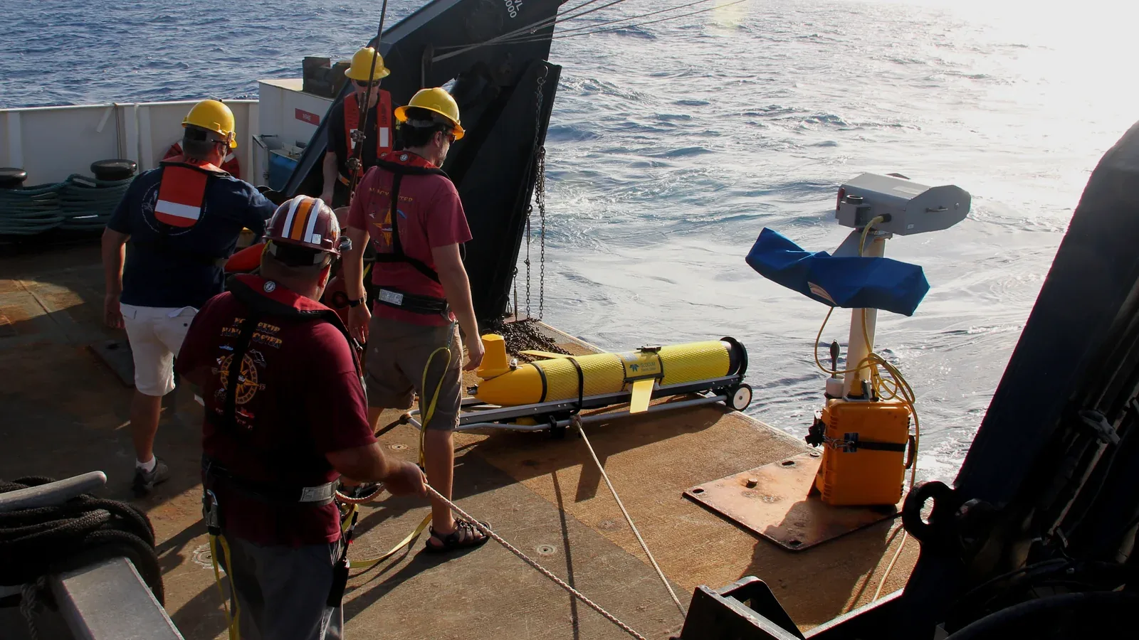
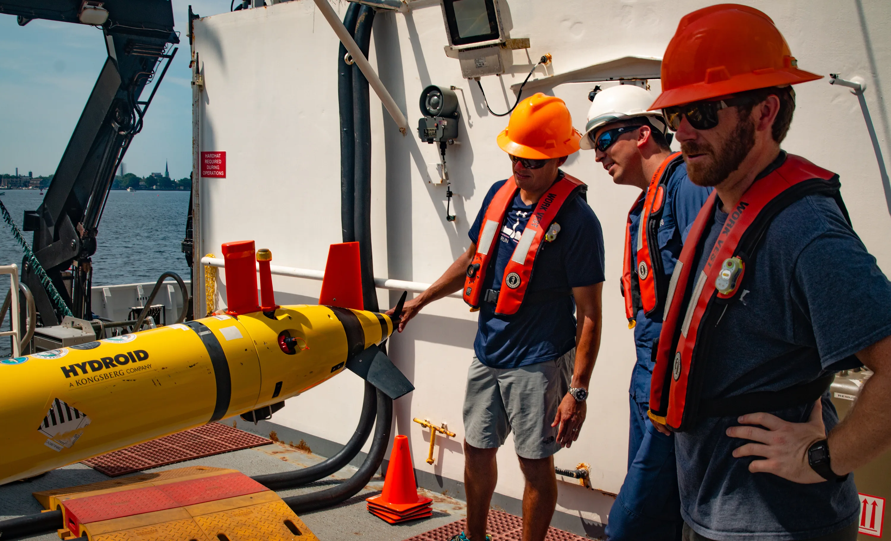
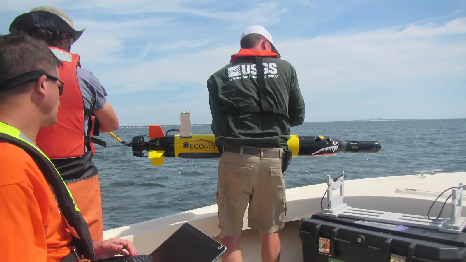
An AUV launch and recovery system commonly combines a handling frame, vehicle cradle, lifting equipment and a release or capture device. WHOI's documented REMUS arrangement illustrates surface handling: an A-frame rotates the supported vehicle beyond the stern, a docking head damps swinging, and the vehicle is lowered tail first before release. Those details belong to that installation, rather than every REMUS or AUV system. WHOI's LARS description shows why a cradle is part of motion control as well as storage.
Submerged capture moves the rendezvous below the disturbed surface. Kongsberg's March 2020 Subsea AUV LARS documentation describes a heave-compensated cradle lowered beneath the splash zone. The returning HUGIN uses its navigation system and a MicroPAP acoustic positioning unit at the LARS to approach, enter the cradle and lock in before hoisting. That adds a navigation-and-capture interface to the lifting machinery. It does not establish compatibility with an arbitrary AUV. Kongsberg technical sheet.
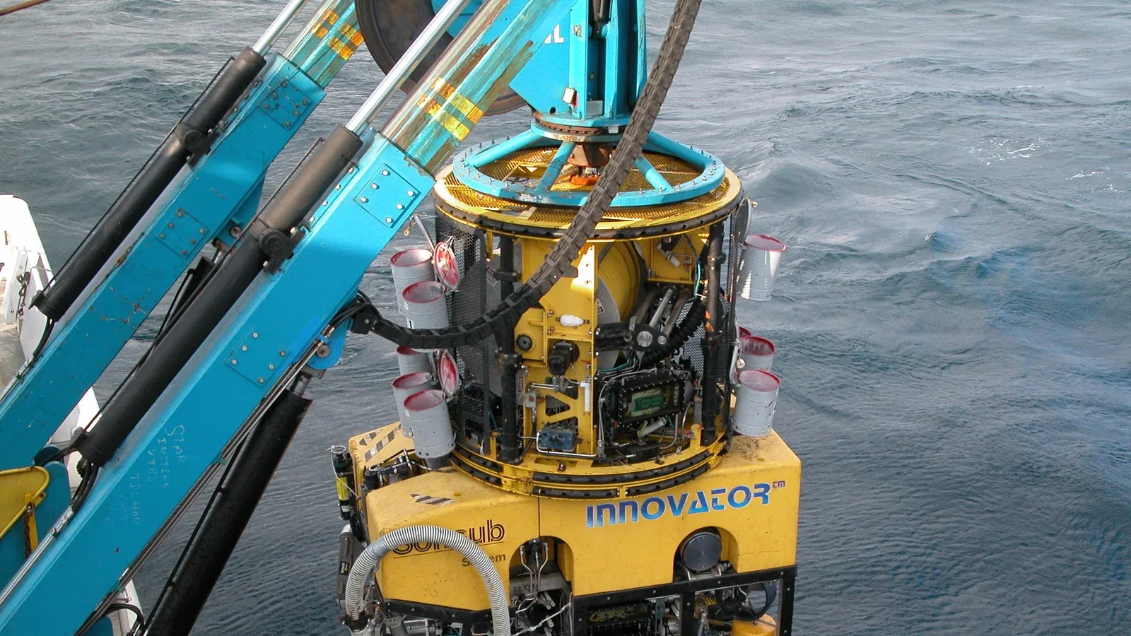
For a tethered ROV, the handling arrangement can remain involved throughout the dive. A surface winch pays out and retrieves the main umbilical; some configurations add a tether management system (TMS), often a cage or intermediate assembly, that manages the vehicle's local tether. WHOI's documented Jason/Medea arrangement illustrates the related two-body principle: the intermediate body separates much of the ship-induced cable motion from the working vehicle. It is a particular configuration, not a claim that every ROV uses a TMS or that Medea is identical to a tether-storage cage. WHOI Jason FAQs.
Architecture comparison
| Arrangement | What must happen at recovery | Main integration question |
|---|---|---|
| Surface AUV handling | Establish the recovery attachment and bring the vehicle under mechanical restraint | Can the handling geometry control the vehicle near the hull? |
| Submerged AUV cradle | Navigate to the cradle, enter it and confirm capture before lifting | What happens if approach or latch confirmation fails? |
| Tethered ROV handling | Manage the cable and, where fitted, recover the vehicle into its TMS before bringing the assembly aboard | Which cable, termination and structure carry each load? |
This comparison synthesizes the WHOI and Kongsberg examples above. The questions are engineering interpretation, not manufacturer operating procedures.
How support transfers between deck and water
Think of the sequence as a series of changes in physical support. On deck, the cradle or securing arrangement holds the vehicle. During transfer over the side or stern, the handling structure and lifting connection carry it. After immersion and release, an AUV supports and propels itself; a tethered configuration retains its cable connection. Recovery must re-establish the intended support before the vehicle is lifted clear.
An interface review should distinguish more than “launch” and “recover.” They include secured, lifted, overboard, immersed, released, captured and stowed. The REMUS example retains cradle support during frame rotation; Kongsberg's submerged system locks the vehicle before lifting. Commanding a latch to close and confirming that it has captured the vehicle are different states. These examples support a practical design question: what confirms that the next load path is ready before the previous restraint is removed?
For an ROV, separate the signal path from the structural load path. A cable can carry power or data without being an approved lifting connection. The particular umbilical, termination and docking arrangement determine how loads reach the frame. MacArtney's MERMAC R documentation lists handling-frame integration, level wind for cable spooling and electro-optical slip-ring options. Review the selected configuration rather than treating that options list as an assembled-system specification.
A useful installation drawing follows both paths: vehicle-to-vessel structural support, and vehicle-to-control-room power and communications. Put the attachment limits and connection ownership on that drawing so that a cable change cannot silently change the lifting arrangement.
What motion compensation changes
Active heave compensation (AHC) adjusts handling motion to counter the vessel's vertical movement. MacArtney offers it on MERMAC R winches for tethered equipment. It can reduce the motion passed into the suspended system, but the supplier description does not establish a universal operating sea state or eliminate lateral movement and hull-clearance constraints.
Passive compensation and active control can also be combined. SMD describes a project using tandem winches and both active and passive heave compensation, with air and glycol hydraulics. Its explanation emphasizes reducing the demand for active correction. This is a specific design example of trading additional machinery and control integration against power demand and motion control, rather than proof that one drive architecture always uses less energy. SMD project description.
For a proposed installation, ask for the compensation travel, speed, load range and behavior when a limit is reached. These are engineering review questions: a compensation label is insufficient to describe how the equipment behaves under the expected vessel motion. Ask separately about loss of power and loss of motion-reference data.
Submerged capture addresses another part of the problem by moving engagement away from the splash zone. It still requires a controlled lift through that zone after capture. The vehicle, cradle and ship remain a coupled handling system; a calm-looking docking location cannot substitute for an installation-specific recovery envelope.
Interfaces to settle before installation
The following checklist translates the cited mechanisms into information an integrator should request. It is a design-review aid, not a commissioning procedure.
Mechanical interface. Establish vehicle and payload configurations, lifting points, cradle contact areas, allowable attachment loads and clearance through the whole handling arc. For an ROV/TMS assembly, identify the supported combination explicitly. Include the vessel foundation and securing arrangement in the review, rather than stopping at the winch base.
Power interface. Identify normal power demand, compensation demand and which functions remain available following an interruption. SMD's combined compensation example makes host-vessel power a concrete design input. For an AUV, specify the reserve needed for the planned return and another approach attempt; battery management systems explain why stored energy estimates and available power deserve separate attention.
Navigation interface. For autonomous capture, define the docking reference, observation timing, quality flags and behavior when the target cannot be resolved. The sensor-fusion explanation provides background on combining observations consistently. Underwater acoustic communications explains the separate communication constraints; an acoustic positioning observation should not be assumed to provide a complete command link.
Control and crew interface. Assign who can authorize release, stop movement and confirm secure capture. Ask how disagreement between a command and physical feedback is presented. Include communications between the bridge, deck operator and vehicle control room, because a vessel maneuver and a winch action can affect the same suspended assembly.
Failures that the recovery plan must cover
Documented incidents show why successful routine operation and a recent load test are incomplete evidence of reliability.
In IMCA's 2021 ROV main-lift incident, an umbilical termination slipped and the ROV/TMS assembly fell to the seabed. It had recently been load tested. The investigation identified termination geometry and preparation problems as well as excessive docking force; corrective actions included a larger cone and docking-head damper adjustment. The relevant lesson is to review termination construction and docking loads together. The report does not establish a failure rate for ROV systems.
Recovery after a failure introduces its own loads. IMCA's 2013 incident report describes an initial umbilical separation followed by a lifting-sling failure during emergency recovery, causing further damage. An alternative attachment is therefore an engineering decision to prepare in advance, rather than an assumption that any accessible point will carry the casualty.
Loss of ship power can defeat more than the lifting drive. In WHOI's January 2023 Jason expedition account, a ship-wide outage affected propulsion and winch power while Jason and Medea were near steep underwater terrain. Jason's positive buoyancy did not allow it to escape independently of the tethered arrangement. Recovery depended on restoring winch power while managing the drifting vessel.
Use those cases to make the review specific:
- For incomplete capture, define how uncertain latch feedback prevents a premature lift and what retreat or retry remains possible.
- For termination damage or a snag, identify inspection triggers and the engineered alternative recovery attachment.
- For power loss, identify the remaining holding, communication and recovery functions, including dependencies shared with vessel propulsion.
- For an unavailable autonomous docking target, establish the vehicle's return, waiting or alternative recovery behavior and its energy limit.
Review these responses through the equipment manuals, engineering analysis and controlled demonstrations appropriate to the hazard. Do not introduce a real load-path or power failure offshore merely to demonstrate the response; agree on a controlled verification method with the responsible engineering and vessel teams.
Match the system to the mission
For repeat AUV surveys, examine the complete return-to-deck cycle, including acquisition, capture attempts, securing and turnaround. A submerged cradle may suit a program that can integrate its navigation and locking interfaces; surface handling may suit a vessel with an established compatible recovery arrangement. The cited designs do not support a universal winner or a transferable wave-height limit.
For tethered inspection and intervention, evaluate umbilical management, the supported ROV/TMS configuration and station-keeping dependencies throughout the task. For a vessel of opportunity, request installation drawings and power requirements early: containerized transport does not by itself prove that the deck, clearances and recovery arrangements are compatible.
For that walk-through, prepare a state-by-state interface record. Beside each transition, identify the current support, the intended next support, the feedback confirming engagement and the person or system authorized to proceed. Keep an uncertain indication separate from a confirmed physical state. Attach the applicable drawing and equipment instruction to each entry, including the selected vehicle and payload configuration. This proposed record makes the article's load-path question traceable through the actual installation. It is not a lifting procedure or an independent determination that an attachment is adequate. The responsible engineering and vessel teams must resolve any missing evidence before accepting the recovery arrangement.
Before selecting a LARS, ask the supplier and vessel integrator to walk through one complete recovery for the exact vehicle and payload, then explain one interrupted recovery at each change of support. Record the operating envelope, observable capture state, load path and fallback authority. That exercise makes the system boundary clear enough to compare proposals on more than lift capacity.
Sources
- WHOI: Launch and Recovery Systems. Institutional description of the REMUS stern-handling mechanism.
- Kongsberg: Subsea AUV LARS, March 2020. Manufacturer technical sheet describing submerged HUGIN capture.
- WHOI: Jason FAQs. Institutional account of a Jason/Medea configuration and tether arrangement.
- MacArtney: MERMAC R. Manufacturer documentation for ROV winch components and compensation options.
- SMD: LARS project development. Manufacturer project account of combined active and passive compensation.
- IMCA: ROV main lift failure, 2021. Industry incident report on termination construction and docking forces.
- IMCA: Loss of ROV and damage during recovery, 2013. Industry incident report on primary and emergency lifting failures.
- WHOI NDSF: The importance of having a plan B, 2023. Expedition account of power loss and Jason/Medea recovery.
Last checked: September 11, 2026.