When satellite navigation is unavailable or untrustworthy, an unmanned aircraft does not replace GPS with one equivalent sensor. It replaces a convenient global reference with a navigation stack. An inertial measurement unit propagates attitude, velocity, and position at high rate, while cameras, lidar, radar, barometric altitude, air data, terrain, landmarks, or local radio references periodically correct the drift. Software estimates the vehicle state and its uncertainty, then decides which measurements are credible.
The right replacement therefore depends on where and how the aircraft must fly. A small indoor inspection aircraft may use visual-inertial odometry and lidar mapping. A low-altitude aircraft over mapped terrain may combine inertial navigation with terrain or image matching. A vehicle inside a prepared site may use local radio ranging. No layer works everywhere, so the operational answer also needs integrity monitoring and a defined response when the remaining solution cannot support the mission. A safe response may be to hold briefly, retrace a locally mapped path, divert, or land, depending on the aircraft and airspace.
GPS loss is a state-estimation problem
GPS is the United States' satellite navigation system and one member of the broader global navigation satellite system, or GNSS, family. A receiver can deliver global position, velocity, and time with little infrastructure on the vehicle. Losing it removes more than a moving dot on a map. It can also remove a shared time reference and the absolute correction that has been containing inertial error.
An IMU measures angular rate and specific force. Integrating those measurements lets the navigation computer propagate motion without an external signal, but small sensor biases and alignment errors accumulate. Better inertial sensors generally slow that error growth; they do not make drift disappear. This is why a resilient design separates two jobs:
- Propagation: maintain a continuous estimate through rapid motion and short gaps.
- Correction: observe something external or otherwise bounded so accumulated error can be reduced.
A third job is just as important: integrity. The system must determine whether a correction is timely, geometrically useful, internally consistent, and independent enough to trust. The U.S. Department of Transportation's Complementary PNT Action Plan warns that common-mode faults can defeat fusion-based monitoring. More inputs are not necessarily more resilient if they share the same clock, map, antenna, preprocessing, or corrupted reference.
Verified policy context: NIST states that GPS transmissions can be disrupted unintentionally or intentionally and frames resilience as a risk-management problem that includes identifying dependencies, detecting disruption or manipulation, and managing the consequences (NIST). That guidance is not an aircraft approval standard, but its dependency-first approach is useful for system design.
What each layer contributes
The table describes engineering roles, not guaranteed performance. Actual accuracy depends on the sensor, installation, estimator, environment, maps, computing platform, and validation evidence.
| Navigation layer | What it contributes | Where it is useful | Characteristic weakness | Implementation question |
|---|---|---|---|---|
| IMU and inertial navigation | High-rate attitude and motion propagation | Every aircraft, including fast transitions and brief outages | Bias, scale-factor, thermal, vibration, and alignment errors accumulate | How quickly does mission-relevant error grow across the specified temperature and vibration range? |
| Camera and visual-inertial odometry | Relative motion from tracked image features, fused with inertial motion | Indoor spaces, structures, urban scenes, and textured terrain | Darkness, glare, haze, repetitive patterns, moving objects, and weak texture | Which lighting, speed, altitude, and scene conditions bound performance? |
| Lidar or radar odometry and mapping | Relative motion or map matching from measured structure | Buildings, corridors, terrain, and conditions suited to the selected wavelength | Sparse geometry, multipath, obscurants, precipitation, range limits, and map change | Does the sensor provide a genuinely independent correction or only reinforce the same local map? |
| Terrain or landmark matching | Absolute or map-relative position from known features | Mapped routes and regions with distinctive, current features | Wrong datum, stale maps, seasonal change, repeated terrain, and viewpoint mismatch | How are map version, coordinate frame, and match confidence controlled? |
| Barometer and radar or lidar altimeter | Vertical constraints, height change, or range to the surface | Altitude hold, landing, and terrain-relative flight | Pressure changes, surface reflectivity, slope, vegetation, and confusing range returns | Is the output height above a surface, pressure altitude, or height in the mission datum? |
| Magnetometer and air data | Heading aid, airspeed, and aerodynamic consistency checks | Open areas with characterized magnetic conditions and forward flight | Motors, wiring, steel structures, local magnetic fields, wind uncertainty, and airflow installation error | Can the estimator detect a locally corrupted heading or airspeed measurement? |
| Local radio or complementary PNT | Ranges, bearings, position, or time from site infrastructure or signals of opportunity | Warehouses, campuses, ports, test sites, and prepared corridors | Coverage, interference, authentication, geometry, shared infrastructure, and regulatory constraints | Who owns, surveys, monitors, secures, and maintains the reference network? |
This comparison exposes a frequent purchasing mistake. A component specification may quote camera resolution, IMU bias stability, lidar range, or radio accuracy, but the mission uses the integrated state estimate. Interfaces, timestamp quality, sensor placement, calibration, estimator tuning, processing latency, and fault logic can dominate the result. Ask for evidence at the system output and under the intended dynamics, not only a sensor data sheet.
Match the correction to the flight environment
Decision guide
| Operating setting | Likely primary correction | Useful complementary checks | Condition that can invalidate the concept |
|---|---|---|---|
| Indoor or enclosed inspection | Visual-inertial or lidar-inertial localization against a local map | Range to nearby surfaces, barometric trend, guarded flight volume | Smoke, darkness, repeated corridors, featureless walls, or a changed layout defeats localization |
| Low-altitude infrastructure route | Visual, lidar, or radar odometry with mapped landmarks where available | Air data, altitude sensing, terrain clearance, route consistency | Vegetation, traffic, reflective surfaces, occlusion, or viewpoint change removes dependable matches |
| Prepared industrial site | Surveyed local radio ranging combined with inertial and local perception | Map matching, antenna health, reference-station monitoring | Poor anchor geometry, interference, lost time synchronization, or compromised site infrastructure |
| Terrain-relative transit | Terrain or image matching that periodically bounds inertial drift | Barometric and radar altitude, air data, route-level plausibility | Flat or repetitive terrain, stale elevation data, cloud, snow, or insufficient sensor resolution |
| Precision approach or landing | Relative localization to a verified landing area or installed reference | Altitude and closure-rate sensing, obstacle perception, inertial continuity | The landing reference is obscured, moved, poorly surveyed, or outside the qualified approach envelope |
The table is deliberately conditional. "GNSS-denied capable" without a named environment, outage duration, required containment, and failure response is not a useful requirement. Indoor position hold for five minutes and accurate navigation across a long route are different problems even when both exclude satellite signals.
A 2020 NASA Spinoff account describes NASA-funded work in which Near Earth Autonomy combined lidar, inertial sensors, cameras, and simultaneous localization and mapping for GPS-free drone navigation. Government account, not independent product test: the page documents the agency's technology-transfer story and prototype work. It should not be read as a current specification, a certification, or proof that the same stack works in every scene.
NIST reports another instructive architecture from Penn State's Autonomous Robotics Competition Club. The team's public-safety UAS solution compared visual-inertial odometry with GPS, incorporated the difference into quality checks, and switched to the alternate position sensor when the GPS-derived local position diverged (NIST ARCC). Government-reported competition result: this is a concrete fault-detection pattern, not a general assurance that any VIO backup will detect every spoofing trajectory.
Design for plausible wrong answers
An obvious outage is often easier to handle than a convincing false solution. Jamming may cause lost tracking or degraded measurements. Spoofing can present a smooth, plausible position that is wrong. Perception can fail just as quietly when repeated windows create a false visual match, a map uses the wrong datum, or a timestamp offset makes individually valid measurements inconsistent.
Failure-mode guide
| Failure mode | What the system may observe | Detection or isolation evidence | Credible response to define before flight |
|---|---|---|---|
| GNSS interference or blockage | Fewer tracked signals, inconsistent measurements, or no solution | Receiver diagnostics plus disagreement with independent inertial and local references | Exclude the input, continue only within the demonstrated drift budget, or enter the contingency plan |
| Gradual false GNSS position | Smooth position that conflicts slowly with local motion or features | Innovation checks, multi-hypothesis logic, authenticated or independent references, and route plausibility | Quarantine the suspect source rather than averaging the conflict away |
| Camera degradation | Feature count falls or tracked features become geometrically weak | Image-quality, feature-distribution, reprojection, and estimator-consistency monitors | Change sensor weighting, use another modality, restrict motion, or leave the affected area |
| Lidar or radar scene ambiguity | Apparently stable alignment to the wrong structure or poor registration | Match residuals, geometry metrics, map consistency, and comparison with another modality | Reject the match and avoid claiming bounded global position until a valid correction returns |
| IMU temperature or vibration error | Growing attitude, velocity, or position residuals | Temperature compensation, vibration monitoring, redundant-channel comparison, and calibration checks | Reduce the allowed unaided interval and transition before containment is lost |
| Altitude-reference error | Slow vertical offset or incorrect surface-relative height | Cross-check barometer, range sensor, terrain, and aircraft dynamics | Increase terrain clearance, discontinue the approach, divert, or land at a verified location |
| Map, datum, or time mismatch | Consistent but displaced localization | Controlled coordinate transformations, map identity, clock-health checks, and surveyed test points | Block use of the affected absolute correction until configuration is restored |
| Compute, bus, or timestamp fault | Delayed or out-of-sequence measurements and estimator jumps | End-to-end latency monitoring, sequence checks, processor health, and independent watchdogs | Revert to a bounded degraded mode or execute the flight-termination response |
| Shared-reference failure | Several sensors agree because they inherit the same bad source | Documented dependency graph and at least one independent challenge signal | Treat correlated sources as one layer, then fall back based on remaining integrity |
This is why a return-to-home command is not automatically a GNSS-denial strategy. It may depend on the same untrusted global position that triggered the contingency. The behavior must be tied to what the aircraft can still establish: local pose, terrain clearance, a verified route segment, a relative landing reference, or only attitude stabilization. The operator also needs an honest indication of solution mode and uncertainty, not merely a green position icon.
What ground and underwater robots teach aircraft designers
Ground vehicles gain strong motion constraints. Wheel encoders can estimate travel, steering geometry constrains likely motion, and a vehicle can sometimes stop while localization recovers. Those advantages bring their own faults. Wheel slip corrupts odometry, vegetation or dust changes perception, and repeated warehouse aisles can create false map matches. The transferable lesson is to exploit domain-specific constraints without mistaking them for independent truth.
Aircraft have less forgiving dynamics. Wind separates air-relative motion from ground-relative motion, vibration reaches inertial and imaging sensors, and the vehicle cannot always pause safely. Aerial imagery also changes sharply with altitude, attitude, lighting, season, and viewing angle. These differences favor early detection, explicit uncertainty bounds, and contingency triggers with enough energy and altitude remaining to act.
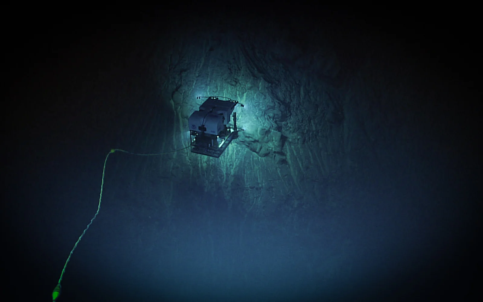
Underwater vehicles live with satellite denial as a normal physical condition because GNSS radio signals do not penetrate seawater. They commonly combine inertial sensing with depth, Doppler velocity, acoustic references, and periodic surface fixes. NOAA's low-power navigation overview describes an architecture in which a GPS-equipped surface vehicle transmits and submerged gliders listen for acoustic range and bearing information. The receiver-side approach reduces underwater transmission demand and can serve multiple vehicles.
A NOAA-hosted research paper on that one-way travel-time inverted ultra-short baseline system reports a 1.1 W active receiver and better than plus or minus 5 degrees of azimuth at slant ranges beyond 1,500 meters under the reported low-tilt trial conditions (Jakuba and colleagues). Research result with stated limits: the authors also reported noisy fixes in parts of the Seaglider ascent and said the results were not yet suited to autonomous real-time navigation. That combination of measured performance and disclosed failure conditions is more useful than a single best-case number.
The underwater example also reveals a dependency trap. Moving the GNSS receiver to a surface reference can help submerged vehicles, but the full architecture still inherits that reference unless it has another way to establish position and time. DARPA's completed POSYDON program pursued ocean-basin positioning from long-range acoustic sources. Government program description: its page states aims and phased work, not a currently available service or a performance guarantee.
Better inertial sensing changes the budget, not the architecture
DARPA's 2026 PINPOINT program is investigating compact MEMS inertial technology intended to reduce reliance on external signals. The agency describes a package about the size of a Rubik's Cube and an aim of GPS-quality precision over multi-hour missions (DARPA PINPOINT). Program target: those size and performance figures are research goals. They are not verified commercial specifications or evidence that fielded aircraft can remove all aiding sensors.
If future compact IMUs drift much more slowly, they could extend the interval between corrections and keep an aircraft inside its error budget through longer outages. Editorially, that would change sensor, energy, and mission tradeoffs, but not the need to monitor installation errors, software faults, initialization, time, and the eventual growth of uncertainty. A better propagator makes corrections less frequent. It does not make every failure observable.
The DOT PNT Strategic Plan promotes multiple and diverse complementary PNT technologies for resilient civil use. Its companion action plan also treats complementary PNT as a layered system-of-systems and calls for standards, monitoring, challenged testing, and domain-specific adoption. Editorial inference: for unmanned aircraft buyers, diversity should be evaluated at the failure-source level, not by counting boxes or brand names.
Questions for an implementation review
Before selecting hardware or accepting a "GPS-free" claim, turn the mission into testable questions:
- What position, velocity, attitude, altitude, and time errors can the mission tolerate, and for how long?
- Is the threat blockage, jamming, spoofing, infrastructure loss, map error, or several of these together?
- Which layer propagates the state, which layers correct it, and which failures are shared?
- What environment supplies observable features or references across the complete route and altitude range?
- What happens at night, over water or snow, in rain, haze, dust, smoke, glare, vibration, or seasonal change?
- How are extrinsic calibration, map datum, magnetic calibration, antenna placement, and timestamps established and maintained?
- What uncertainty and integrity outputs reach the flight controller and operator, at what update rate and latency?
- Which measurement is rejected when two credible sources disagree, and what evidence drives that decision?
- How much flight time, energy, and terrain clearance remain when the contingency threshold is crossed?
- Can the fallback operate without the failed source, including home position, time, communications, maps, and landing reference?
- What logged evidence supports repeatable evaluation, regression testing, incident reconstruction, and software updates?
- Which claims are measured integrated-system results, which are supplier specifications, and which are research or program targets?
Procurement should ask for an error budget, dependency diagram, interface and time-synchronization design, defined degraded modes, environmental limits, and evidence from representative challenged scenarios. Acceptance criteria should measure the navigation output and resulting flight behavior. No sensor label, algorithm name, or nominal accuracy substitutes for that system evidence.
Sources and scope
This analysis uses U.S. government PNT guidance, government program descriptions, a NASA technology-transfer account, a NIST competition profile, and NOAA-hosted underwater research. Program aims and team claims are identified as such; research figures retain their reported conditions and limitations. The article offers engineering and procurement questions, not hands-on test results, flight approval, certification guidance, or a claim that one stack is suitable for every aircraft or operating environment.