EOD robots are remotely operated machines that let explosive ordnance disposal specialists inspect hazardous scenes and position tools while remaining away from the immediate hazard. Their effectiveness depends on a connected system: the chassis places the arm, the manipulator positions its gripper or tool, cameras show the work, and the operator directs movement through a communications link.
Useful capability requires more than arm strength. The operator also needs a clear view of the contact point, predictable controls, and feedback that arrives soon enough to guide the next movement. NIST's response-robot program consequently measures mobility, dexterity, sensing, communications, and operator proficiency as distinct capabilities.
On This Page
- The robot and control station form one system
- Manipulator reach depends on the task and posture
- Cameras must show both the scene and the contact point
- Operator control depends on timely feedback
- Interfaces and failures cross component boundaries
- Different applications expose different limits
- Evaluate the robot and operator together
The robot and control station form one system
A typical ground EOD system combines a mobile base, onboard power and electronics, an articulated manipulator, cameras and illumination, a communications system, and an operator control unit, often shortened to OCU. Mission equipment adds a separate integration task. An inspection camera, detector, or other tool needs a usable mount, suitable power, and a way to control it and receive its output.
The PackBot 525 illustrates this arrangement. Teledyne FLIR describes a manipulator, HD cameras, a laser rangefinder, accessory ports, an MPU5 radio, and a touchscreen uPoint controller. These are documented features of that platform, not a mandatory configuration for every EOD robot.
Two feedback paths explain how it works. Inside the robot, a motor controller uses sensor feedback to regulate an actuator's movement. Across the remote link, the operator watches the result and chooses the next command. The first loop controls the mechanism; the second connects the mechanism to the human's understanding of the scene.
Modern Robotics' control overview describes the underlying sequence: requested motion and measured state enter the controller, motor amplifiers supply power, and sensors report the resulting movement. A remote control interface sits above those local controls. A working video display does not, by itself, prove that every actuator is responding correctly.
Manipulator reach depends on the task and posture
An articulated arm changes the position and orientation of its end effector, the gripper or tool at its tip. Its degrees of freedom describe independent ways the mechanism can move. For an engineering evaluation, distinguish reaching a point from reaching it with the tool facing the required direction and with clearance around the arm. Ask which motions the quoted joint count includes, especially wrist rotation and gripper opening.
Load changes with geometry
The load at the tip creates forces and turning moments at the joints. Modern Robotics' treatment of arm statics relates these loads to joint forces and torques through the arm's configuration. The practical consequence is that a single maximum lifting figure cannot describe the whole working envelope.
For a simplified horizontal lever, moment = load force × horizontal distance. With the same load, doubling that distance doubles its contribution to the moment about the supporting joint. This illustrates the geometry only; it is not a robot load rating and omits the arm's own weight, movement, and structural limits.
Ask for the permitted load at the intended reach, height, and tool orientation, including the installed tool's mass. Also establish whether the quoted value describes gripping, lifting, carrying on the chassis, or towing. Those actions load different parts of the system.
The base must support the arm's work
The chassis provides the support beneath the manipulator. An arm demonstration on a level surface leaves its working envelope on slopes, steps, or partially supported tracks unverified. Treat the loaded arm posture and chassis posture as one configuration to be demonstrated.
This is why mobility and manipulation need separate evidence before being combined into a mission. NIST's ground-robot test guidance organizes capability evaluation around repeatable tasks, rather than defining one universally suitable robot.
Cameras must show both the scene and the contact point
An overview helps the operator understand where the robot is. A close view helps show where the gripper or tool is relative to an object. Neither view should be assumed to cover the other task: an arm can obscure the scene, and a tightly framed contact point can hide nearby obstacles.
NIST's C-IED robot training examples include switching between forward and rear views while maneuvering, and controlling pan, tilt, zoom, and focus across near and distant targets. That combination is more revealing than camera count alone.
Pan and tilt aim the camera; zoom changes framing; focus determines which distances appear sharp. For a close manipulation task, ask whether the operator can see the contact area throughout the arm's intended movement, including under the installed lighting. For driving, check that the selected view makes the relevant ground contacts and clearance understandable.
Depth perception adds another question. A 2010 technical paper on TALON stereo vision describes an upgrade with stereo mast and gripper cameras and a matching display, assessed for driving, manipulation, and surveillance. It demonstrates a system-level approach to depth viewing. Its abstract supplies neither a universal accuracy-improvement figure nor an equipment list for current TALON variants.
Evaluate the image on the operator's actual display. The useful result is the detail and spatial relationship the person can recognize there, through the complete camera and transmission path. NIST's response-robot standardization paper describes visual-acuity testing using what an operator can read on the OCU screen. Sensor resolution alone leaves that question unanswered.
Operator control depends on timely feedback
The operator sends movement and equipment commands; the robot returns video and status. A control layout must make clear which robot, camera, or mechanism is selected and what the controls will do. Where a platform offers assisted movement or stored positions, establish exactly what the software controls and what the operator must still judge.
PackBot's documented uPoint interface can select among connected robots. QinetiQ's TALON family page also lists autonomy and mapping. Those descriptions do not mean either platform independently decides how to handle every explosive hazard. Capabilities need to be tied to the specific robot, software, and fitted equipment.
Communications quality has several dimensions. The command can arrive late, the returned picture can be stale, or the connection can fail entirely. NIST's radio-attenuation study identifies reflections, absorption, and interference as factors affecting range, reliability, and timeliness. A distance achieved in open line of sight leaves performance inside a particular building unverified.
The engineering consequence is to assess control and viewing together under representative link conditions. A sharp frozen picture is not current feedback. Specify how the interface identifies stale video, missing telemetry, and lost command communication, and demonstrate the configured response to each. Do not infer a universal stop, hold, or return behavior from the presence of a radio link.
Interfaces and failures cross component boundaries
Adding a sensor or tool changes more than the equipment list. QinetiQ describes camera expansion through input/output ports and lists Interoperability Profile, or IOP, and SAE JAUS AS4 compliance on its TALON page. Such architecture claims are useful starting points, but they do not verify an arbitrary accessory and controller combination.
For a proposed integration, request the exact mechanical attachment, supply requirements, connector pinout, protocol and software versions, supported commands, and returned status. Confirm that the operator can use the accessory while retaining the views needed to maneuver. A physically connected accessory is not yet a demonstrated remote function.
Questions that expose failures between components
The following table translates the cited control, communications, and NIST evaluation principles into engineering review questions. These are potential failure paths, not reported defects in a named product.
| Observation or change | Function at risk | What to establish in a controlled demonstration |
|---|---|---|
| Video freezes while the interface remains open | Operator loses current visual feedback | How stale imagery is indicated and which movement functions remain available |
| A command is sent but the arm does not move | Requested motion is not completed | Which feedback distinguishes a limit, actuator fault, or rejected command |
| A tool blocks the close camera | Contact area becomes difficult to judge | Whether another usable view covers the intended working envelope |
| An accessory shares power with essential electronics | One electrical fault may affect multiple functions | Power limits, fault isolation, and the documented response to an accessory fault |
| The radio connection is interrupted | Remote commands or feedback become unavailable | The exact configured behavior of drive, arm, and attached equipment |
| The battery approaches its operating limit under the fitted load | Remaining work and recovery become uncertain | Status indications and demonstrated endurance for that configuration |
Source basis: Modern Robotics control principles, NIST radio testing, and NIST's capability categories. The failure questions are editorial engineering synthesis, not reported test results.
Different applications expose different limits
Remote inspection emphasizes camera placement, illumination, and the ability to reach a useful viewpoint. Tool positioning adds loaded reach, orientation, and visibility of the working area. Building access combines maneuvering clearance with communication through the intended structure. These scenarios can require different evidence even when the same robot performs them.
Chemical, biological, radiological, and nuclear sensing, abbreviated CBRN, adds dependence on the specific detector. The PackBot page lists CBRN and hazardous-material applications while noting that sensors are separate. Which substances can be identified, and how readings should be interpreted, depend on the installed detector rather than the platform's carrying capacity.
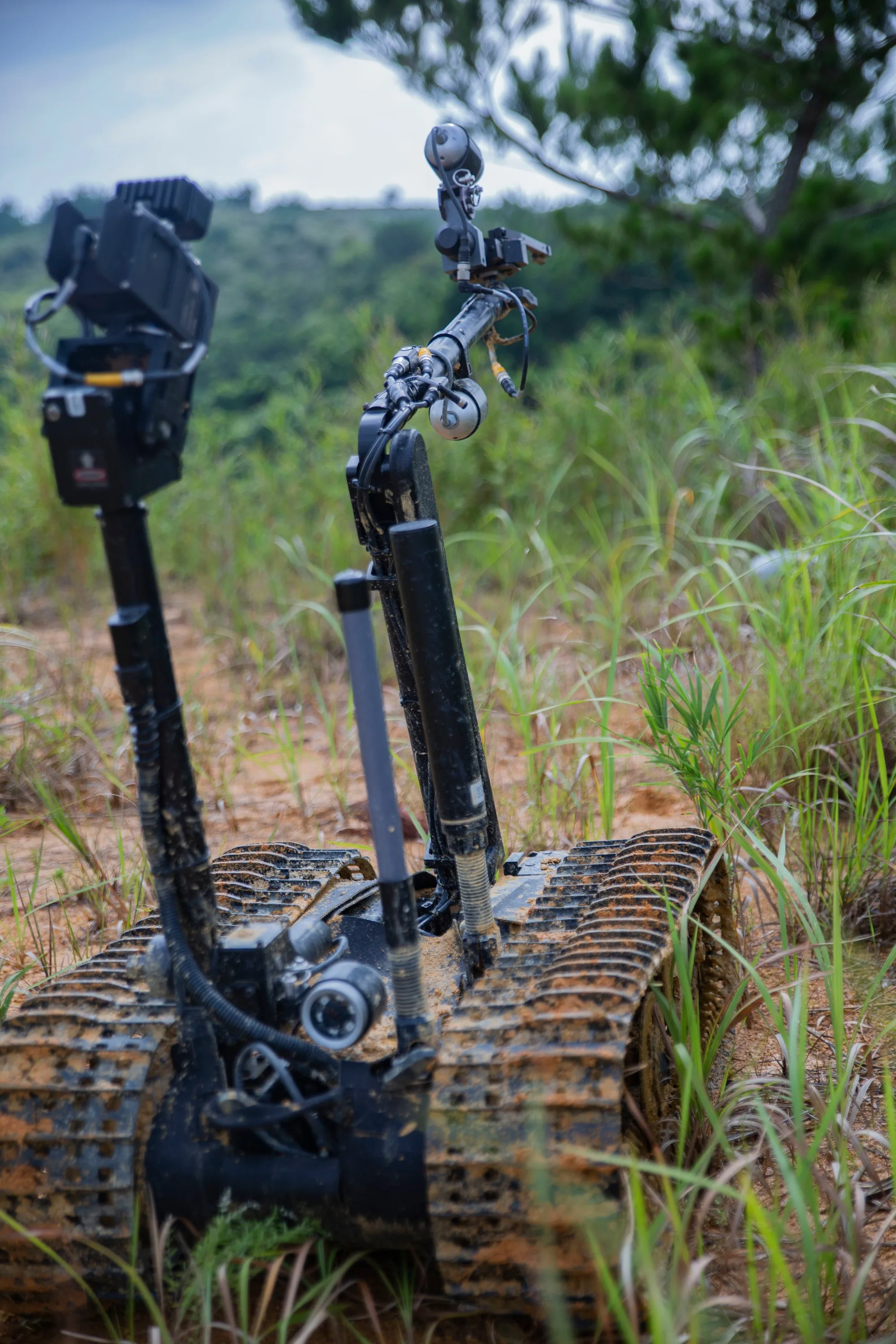
Training is another representative application. The featured Marine Corps photograph from Camp Hansen records a Mark II TALON during training in August 2018. Its visible arm, gripper, cameras, and tracked base illustrate the components discussed here. It is a historical configuration, not a specification for the current TALON family.
Evaluate the robot and operator together
Start with the work the organization needs to perform, then ask for repeatable demonstrations of the relevant capabilities in the proposed configuration. Record the fitted tool, camera views, communications arrangement, load posture, and operating conditions so the result can be interpreted and repeated.
NIST distinguishes standardized test methods from an equipment standard that sets one passing performance level. The organization must choose the capabilities and performance it requires. Its C-IED examples also place operators out of sight of the robot so they depend on the remote interface; watching the machine directly would answer a different question.
An EOD robot is useful when the operator can reach the required location, understand what the cameras show, command the necessary movement, and recognize when the system is no longer responding as expected. Evaluate that complete chain before treating arm strength, camera resolution, or advertised range as a mission capability.
Sources
- NIST: Performance of Emergency Response Robots. Government research program describing capability categories and the distinction between test methods and user-selected performance requirements.
- Teledyne FLIR: PackBot 525. Manufacturer documentation for the named system's components, controller, communications, and sensor-dependent applications.
- Modern Robotics: Control System Overview. University-hosted technical explanation of sensor feedback, controllers, and actuators.
- Modern Robotics: Statics of Open Chains. Technical basis for the relationship between arm configuration, tip loads, and joint forces or torques.
- NIST: Ground Robot Tests. Government guidance on repeatable capability evaluation for response robots.
- NIST: Counter-Improvised Explosive Device Applications. Documented robot training examples covering camera control, maneuvering, and remote operator evaluation.
- Chenault and coauthors: Stereo Vision for Explosive Threat Defeat. Abstract of a paper presented in 2010 describing a TALON stereo-camera and display upgrade; no quantitative result is inferred from the abstract.
- NIST: response-robot standardization paper. Technical discussion of visual-acuity testing through the operator display.
- QinetiQ: TALON Medium-Sized Tactical Robot. Manufacturer description of platform expansion and listed control and interoperability features.
- NISTIR 8243: Response Robot Performance Under Attenuated Radio Conditions. Government research on communications degradation and repeatable radio evaluation.
- DVIDS: Robotics Autonomous, image 4612123. Official Marine Corps photograph documenting the depicted 2018 training scene.
Last checked: September 6, 2026.