An autonomous underwater vehicle (AUV) navigates below the surface by combining an estimate of its motion with measurements that correct accumulated error. An inertial navigation system tracks movement and orientation; a Doppler velocity log measures velocity; pressure provides depth; and acoustic fixes or terrain matching help locate the vehicle. GPS can initialize or update the solution at the surface, but it cannot provide ordinary submerged navigation.
The central design question is how the vehicle will constrain position error throughout the mission, including descent, survey turns, sensor outages, and recovery. A navigation system that works near the seabed may behave very differently during a long transit above it. MBARI's mapping AUV documentation illustrates this directly: acoustic updates support descent until the vehicle can measure motion relative to the bottom.
On This Page
- What each navigation input contributes
- How the onboard estimate is built
- How acoustic fixes and terrain matching correct position
- Interfaces that can undermine good sensors
- What happens when navigation inputs disappear
- Match navigation performance to the mission
- What to establish before choosing an architecture
What each navigation input contributes
These inputs constrain different parts of the vehicle's state: its position, velocity, and orientation. Their presence on an equipment list does not make them interchangeable.
| Input or method | What it contributes | Main dependency or limit |
|---|---|---|
| Inertial measurement unit and navigation software | Propagates orientation, velocity, and position between corrections | Sensor errors accumulate without adequate aiding |
| DVL bottom tracking | Velocity relative to the seabed | Usable bottom echoes and correct installation |
| DVL water tracking | Velocity relative to a sampled water layer | Current must be accounted for to obtain seabed-relative motion |
| Pressure sensor | An input for estimating depth | Does not locate the vehicle horizontally or measure bottom clearance |
| USBL acoustic positioning | Range and direction relative to a compact acoustic array | Acoustic path and the reference platform's position and orientation |
| LBL acoustic positioning | Position constraints from ranges to surveyed seabed transponders | Array geometry, reference coordinates, and sound-speed information |
| Terrain-relative navigation | Position relative to a pre-existing seabed map | Suitable measurements and a map that can support localization |
Source basis: the inertial-navigation research, Nortek manuals, Sonardyne positioning explanations, and WHOI terrain-navigation account listed below. The dependency column is an engineering synthesis, not a comparative accuracy rating.
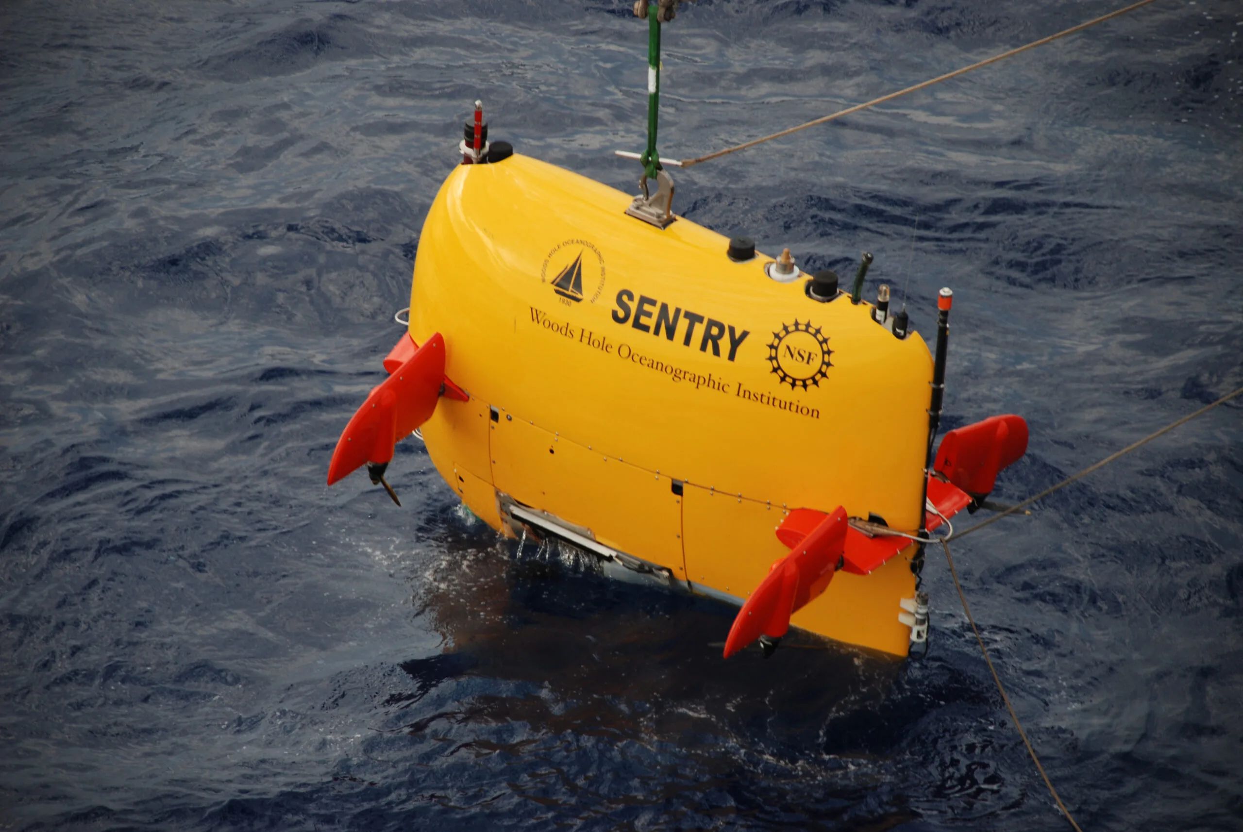
Real research vehicles combine several of these inputs. The National Deep Submergence Facility's Sentry sensor description lists pressure sensing, DVLs, and inertial attitude and navigation equipment. Its navigation display also distinguishes the planned survey lines, completed track, vehicle, and ship. Knowing where the AUV is and knowing what it has actually surveyed are connected tasks.
How the onboard estimate is built
An inertial measurement unit (IMU) contains gyroscopes and accelerometers. The inertial navigation system (INS) combines their measurements with navigation equations to propagate orientation, velocity, and position. Small errors accumulate as those measurements are integrated. An INS therefore needs appropriate aiding for the mission's duration and accuracy requirement.
In Model-Aided Inertial Navigation for Underwater Vehicles, Hegrenæs, Berglund, and Hallingstad describe a Kalman filter using aiding measurements to estimate errors and correct the solution. This mathematical estimator depends on the available measurements and their error models.
A Doppler velocity log (DVL) sends acoustic beams and uses the Doppler shift of their echoes to estimate velocity. In bottom-track mode, the reference is the seabed. In water-track mode, it is a layer of water. Nortek's DVL Operations manual describes both modes, coordinate conventions, and installation requirements.
Water tracking is useful when the bottom is unavailable, but a moving water layer is not a stationary reference. The relationship is a vector sum:
Vehicle velocity relative to Earth = vehicle velocity relative to water + water velocity relative to Earth.
The cited research evaluates current estimation and a vehicle-dynamics model as additional aiding. The results are specific to the studied vehicle and conditions.
Even with bottom tracking, integrating velocity still leaves position dependent on the starting fix, orientation, and measurement errors. The practical distinction is that velocity aiding reduces drift; a referenced position observation can constrain where the accumulated track lies.
Pressure contributes another independent measurement. Depth below the surface and altitude above the seabed are different quantities. An AUV can maintain constant depth while approaching rising terrain. Bottom-clearance control therefore needs suitable range information or terrain knowledge as well as depth. Sentry's documented pressure and sonar instruments illustrate why these functions belong in separate parts of the sensor discussion.
How acoustic fixes and terrain matching correct position
USBL: locate the vehicle from a reference platform
Ultra-short baseline (USBL) positioning uses a compact transducer array, commonly installed below a ship, and an acoustic device on the underwater target. As Sonardyne explains, the system derives range from acoustic travel time and direction from the array's received signals.
That begins as a relative measurement. Converting it into geographic coordinates also requires the reference platform's position, orientation, and installation offsets. A support vessel can therefore contribute GPS-derived position indirectly even though the AUV itself cannot receive GPS underwater.
Tracking and onboard aiding need separate interfaces. A position shown on a ship's screen does not automatically correct the AUV's estimate. MBARI describes relaying USBL positions through an acoustic modem during descent. Ask where the fix is computed, how it reaches the vehicle, and what timestamp accompanies it.
LBL: work relative to a surveyed seabed array
Long baseline (LBL) positioning uses separated transponders with known seabed coordinates. Ranges to those reference points constrain the target's position. Sonardyne's LBL explanation describes array calibration, redundant ranges, and the importance of sound speed, which varies with water conditions.
LBL adds equipment deployment and survey work, but provides a local reference network for repeated operations. Its geographic accuracy also depends on how that network was positioned. Inertially aided sparse arrays are another configuration; a reduced transponder count should be assessed together with vehicle motion, aiding, and fault detection rather than treated as equivalent to a full array.
Terrain matching: use a map as the reference
Terrain-relative navigation compares observations made during the dive with a pre-existing seabed map. WHOI's account of Sentry's terrain-navigation development describes software adapted from MBARI to correct the vehicle's track during repeat surveys of Axial Seamount.
This makes the map part of the navigation system. The engineering implication is that map coverage, registration, and recognizable terrain must be evaluated before relying on it. Repeated or poorly distinguished terrain can leave several plausible matches; a plausible match alone should not be treated as a certain location.
WHOI reported that Sentry repeated its course within ten meters on the final two missions of the 2022 expedition. That is a result from those trials, not a universal terrain-navigation specification or a guarantee of absolute geographic accuracy.
Interfaces that can undermine good sensors
Navigation integration requires more than connecting a serial cable or Ethernet port. The receiving system must understand the meaning, age, and validity of every measurement.
Coordinates and mounting: establish the axis directions, signs, units, and rotation between sensor and vehicle frames. Record the lever arm, meaning the physical offset between a sensor and the chosen navigation reference point. Nortek's operations manual documents mounting-angle and origin information used for INS integration. Those details matter during turns as well as straight travel.
Measurement time: distinguish the time an observation represents from the time its packet arrives. Nortek's 2017 DVL Integrator's Guide defines ping timestamps and offsets between the echo measurement and message output. It also documents network clock synchronization. Use the selected instrument and firmware's actual convention; another manufacturer's similarly named field may mean something different.
For an illustrative timing calculation, suppose a vehicle moves in a straight line at a constant 1.5 meters per second and a position observation is treated as current despite being 0.2 seconds old. The vehicle has traveled 1.5 × 0.2 = 0.30 meters during that interval. These are hypothetical inputs showing motion during latency, not a predicted total navigation error.
Validity and uncertainty: pass status and quality fields with the measurements. The Nortek integrator guide documents explicit invalid-value conventions and quality information. A parser must distinguish a valid zero velocity from missing or invalid data. Reusing the last valid sample indefinitely would conceal an outage.
What happens when navigation inputs disappear
The useful fault question is which constraint has been lost and how long the remaining estimate can support the task. Use the following as integration review questions, not universal automatic responses:
- Bottom lock disappears: does the system recognize loss of seabed-relative velocity, and can it use acoustic aiding, a current-aware water-track estimate, or a validated vehicle model? Inspect the estimated uncertainty during the gap and after reacquisition.
- Acoustic fixes stop or disagree: does the estimator continue propagating position while identifying the missing correction? Check sound-speed inputs, reference geometry, and measurement quality before accepting a large position change.
- Terrain matching is ambiguous: can the estimator retain uncertainty or reject the match instead of snapping to a misleading location? Test against the actual map and expected route.
- A sensor restarts or packets arrive late: are clock changes, stale data, invalid fields, and restored measurements handled explicitly?
These questions follow from the cited estimator research, acoustic reference requirements, and DVL data interfaces. Define the mission response separately: seeking another fix, modifying the survey, or recovering must fit the remaining capability and environment. For example, a recovery plan beneath ice or a structure cannot assume an unobstructed ascent.
Match navigation performance to the mission
Separate absolute accuracy, relative repeatability, and real-time control when reviewing results. A repeat survey may align well with an earlier map while both retain a common geographic offset. A corrected track produced after recovery may improve the data product without improving the route the vehicle already followed.
MBARI documents post-processing that matches overlapping and crossing bathymetric swaths. That makes survey overlap part of the data-processing strategy. It also shows why a final map's precision should not be substituted for the onboard navigation performance used during the dive.
Different applications emphasize different requirements:
- Seafloor mapping: preserve usable positioning through descent, establish bottom tracking, and retain enough survey overlap for the intended processing.
- Repeat geological surveys: prioritize returning to the same reference and distinguish map-relative repeatability from absolute coordinates. The Sentry work at Axial Seamount is a documented example.
- Operations around fixed subsea infrastructure: assess whether a calibrated local acoustic network justifies the deployment effort. Sonardyne identifies subsea installation, metrology, and pipeline positioning among LBL applications.
- Water-column sampling: establish how samples will be located when the bottom cannot be used as a velocity reference. Sentry's sensor description includes sampling at specified depths and survey lines, illustrating why sample location belongs in the navigation requirement.
There is no defensible single accuracy number for all of these architectures. Request the error definition, reference truth, mission duration, distance traveled, aiding availability, and outage conditions behind any figure. Compare configurations using those same conditions.
What to establish before choosing an architecture
Define the required position knowledge for each mission phase and identify the measurement that supplies it. Then examine the longest credible period without that measurement. The architecture is suitable only if its remaining estimate and recovery behavior fit the task through that interval.
For a practical review, request synchronized sensor and navigation logs from a representative mission, including a documented aiding outage and recovery. Confirm the coordinate frames, timestamps, quality flags, acoustic reference survey, and any terrain map used. Finally, separate what was available onboard from what was improved after the dive. That distinction connects the sensor specification to the AUV's actual ability to complete its route and deliver useful data.
Sources
- Hegrenæs, Berglund, and Hallingstad: Model-Aided Inertial Navigation for Underwater Vehicles. ICRA 2008 research preprint describing INS aiding, current estimation, and experimental evaluation of a vehicle model.
- Nortek: DVL Operations, 2018. Manufacturer manual for Doppler operation, coordinate conventions, mounting, and interfaces in the documented models.
- Nortek: DVL Integrator's Guide, 2017. Manufacturer protocol manual for timing, data fields, and invalid measurements; implementation details are version-specific.
- Sonardyne: What is a USBL and how does it work? Manufacturer explanation of acoustic range-and-direction positioning.
- Sonardyne: What is LBL underwater positioning? Manufacturer explanation of seabed arrays, ranging, calibration, sound speed, and applications.
- MBARI: Seafloor Mapping AUV. Research-platform documentation of descent aiding, bottom tracking, survey operations, and post-processing.
- WHOI: How does Sentry know where it is? Institution's January 2023 account of its terrain-navigation development and 2022 trials.
- National Deep Submergence Facility: Sentry Systems, Sensors and Sampling. Operator documentation of navigation instruments, displays, and scientific sampling.
Last checked: September 7, 2026.