Simultaneous localization and mapping (SLAM) lets an unmanned system estimate its position and orientation while building a map from its own sensor observations. The two estimates support each other: motion estimates help place observations, and recognized places help correct accumulated motion error. SLAM is useful when a dependable map or external positioning reference is unavailable. It supplies navigation information; planning and vehicle control remain separate functions.
For engineers choosing a SLAM system, the decisive questions are what the sensors can repeatedly recognize, which map the mission needs, and how the vehicle behaves when tracking or map consistency fails. A convincing map display answers only part of those questions. Cadena and colleagues' SLAM tutorial explains this estimation problem and its dependence on the robot, environment, and required performance.
On This Page
- What SLAM adds to odometry
- How observations become a corrected map
- Choosing the sensing approach
- Connecting SLAM to the vehicle
- Failure modes to expose before deployment
- Applications across unmanned systems
- Evaluate the whole navigation chain
What SLAM adds to odometry
Odometry estimates movement over time. Visual odometry uses images; visual-inertial odometry also uses an inertial measurement unit (IMU), which measures acceleration and angular motion. SLAM adds persistent map use and the ability to associate current observations with previously mapped places. Implementation names overlap, so ask whether a system actually supports loop closure, relocalization, and map reuse.
Loop closure recognizes a previously visited location and adds a constraint that can correct the trajectory and map. Relocalization recovers a pose in a known map after tracking is lost. They solve related but different problems. The ORB-SLAM3 paper distinguishes these operations from short-term motion estimation and from merging previously disconnected maps.
Localization against an existing map can be enough when the environment is already mapped and stable. Building a new map on every mission is a design choice, not a prerequisite for autonomy. Also distinguish map-relative position from geographic position: a locally consistent map does not automatically establish latitude, longitude, or a survey datum. The reference must be defined explicitly, as illustrated by ROS REP 105.
How observations become a corrected map
A practical architecture separates frequent local estimates from broader map optimization. Hess and colleagues' research abstract describes scan-to-submap constraints for loop closure. Cartographer's algorithm documentation explains the processing stages:
- Prepare observations. Filter ranges and compensate for motion during scanning.
- Estimate local motion. Align scans with the current submap.
- Build submaps. Retain locally consistent observations.
- Connect revisited places. Find matches to earlier submaps.
- Optimize globally. Adjust poses to reconcile constraints.
In a pose graph, a node represents a pose and a constraint expresses a measured relationship. Optimization reconciles those relationships; it cannot make a wrong place match true. Similar-looking corridors or repeated structures can produce false associations that distort the map. Geometric checks and rejection of inconsistent matches therefore matter alongside recognition, as the SLAM tutorial's robustness discussion explains.
The output also needs a defined purpose. The ORB-SLAM2 paper distinguishes its sparse reconstruction for localization from dense reconstruction. Cartographer's occupancy grids instead represent how likely cells are to be occupied. Ask for the actual map representation and the interface that converts it into the planner's collision model.
Choosing the sensing approach
Start with the observable environment and the vehicle's installation limits. The following comparison combines documented capabilities with engineering questions to carry into evaluation; it is not a ranking of products.
| Approach | What it uses | Main integration question |
|---|---|---|
| Monocular visual SLAM | A single camera's changing view | How is metric scale established, and what happens when visual tracking is lost? |
| Stereo or RGB-D SLAM | Paired images or color plus depth measurements | Does the camera configuration provide useful depth over the mission's working distances? |
| Visual-inertial SLAM | Camera observations combined with IMU measurements | Are camera calibration, sensor alignment, timing, and initialization adequate? |
| Lidar-inertial SLAM | Range scans combined with IMU measurements | Are scan timing, motion compensation, point format, and sensor transforms correct? |
| Sonar-based SLAM | Acoustic observations, often combined with other navigation inputs | Can the sonar repeatedly match useful features in the intended underwater environment? |
Source basis: the ORB-SLAM2 paper, the ORB-SLAM3 paper, LIO-SAM documentation, and Zhang and colleagues' side-scan sonar research. The questions are editorial synthesis of their documented dependencies, checked September 7, 2026.
Pure monocular geometry has an unknown scale; stereo supplies a metric baseline. Camera occlusion and fast motion can interrupt visual tracking. ORB-SLAM2 paper
Visual-inertial initialization estimates scale and inertial quantities, and unsuitable motion can make it harder. Evaluate initialization and recovery separately from steady tracking, rather than adopting a paper's best error figure as an installed-system promise. ORB-SLAM3 paper
Sensor support is also specific to the implementation. ORB-SLAM3 documents monocular, stereo, RGB-D, and visual-inertial configurations, and requires calibration for the user's camera. LIO-SAM documents per-point scan timing, ring information, and lidar-to-IMU transforms. A compatible connector or generic point-cloud message alone does not establish a working integration. ORB-SLAM3 setup documentation, LIO-SAM input requirements
A sensor can produce data without resolving motion
Observability asks whether the available measurements constrain the state being estimated. The LION research explicitly evaluates when lidar geometry leaves pose poorly constrained. Its odometry and confidence estimates feed a supervisor that can switch between estimation sources. That architecture illustrates why a functioning sensor and a trustworthy pose estimate are separate conditions.
For an integration review, ask whether confidence identifies the poorly constrained motion direction or merely reports that messages are arriving. Then establish what independent information the fallback actually adds. Adding another estimator using the same compromised observations does not, by itself, establish useful redundancy. These are evaluation questions derived from LION's observability and supervision approach, not a recommendation to copy its configuration.
Environmental qualification needs more than a clean laboratory route. NTNU's lidar-degeneracy dataset contains aerial-robot measurements from a geometrically repetitive tunnel and a fog-filled corridor. The authors recorded lidar, radar, and IMU data during manual flight. These cases separate weak scene geometry from obscured returns; they should not be described as evidence that every lidar fails in either environment.
A useful trial matrix therefore varies both the scene and the sensing conditions. For each mission segment, identify the structures expected to constrain motion, the conditions that could hide them, and the indication that would reveal degradation. Include transitions into and out of those conditions. This proposed matrix helps expose a system that recovers eventually but delivers unsuitable estimates during the transition.
Connecting SLAM to the vehicle
Specify the output contract before connecting an estimator to a controller: pose reference, body reference, timestamps, units, velocity convention, uncertainty representation, and reset behavior. Each item changes how the receiver interprets the same numbers.
ROS REP 105 illustrates why two pose references can be useful. The odom reference provides continuous local motion but can drift; map supports longer-term consistency but can change discontinuously after corrections. The usual transform chain is map to odom to base_link. The practical implication is to preserve local control continuity while explicitly handling global corrections and map changes. REP 105 is a ROS convention, not a universal unmanned-system interface standard. REP 105
For an aircraft example, PX4's external-position guide documents MAVLink pose and odometry inputs, coordinate transformations, sensor offsets, and vision-delay configuration. ROS and PX4 body/world conventions can differ. Transforming position without correctly treating orientation and velocity leaves an inconsistent message. The guide also distinguishes observation timing from message arrival timing.
A SLAM library therefore needs an integration layer that delivers the selected autopilot release's expected fields and timing. Verify those requirements against that release; the cited PX4 page tracks its main documentation branch. Test how the receiver responds to missing updates and corrections before relying on the pose stream.
Connect the map to collision checking
A vehicle also needs a representation its planner can use. Nav2's Jazzy costmap documentation describes a layered two-dimensional planning representation with static, obstacle, and inflation plugins, along with robot footprint and unknown-space settings. This is a concrete example of the work downstream of SLAM: the map and current observations must become costs that reflect where the vehicle can travel.
For a ground-robot integration, verify the footprint used for collision checking, how newly detected obstacles enter the costmap, and whether unobserved cells retain an unknown status. Also specify which frame and update timing the planner expects. A correctly localized robot can still receive an unsuitable route if its geometry or planning map is wrong. These checks are engineering implications of the documented costmap inputs; a two-dimensional Nav2 configuration should not be assumed sufficient for an aircraft or underwater vehicle moving through three-dimensional space.
Failure modes to expose before deployment
Use deliberately difficult cases to distinguish a sensor problem from an interface or map problem. These are proposed evaluation checks, not reported tests of a particular vehicle.
| Symptom or condition | Possible mechanism | What to examine |
|---|---|---|
| Tracking disappears during an occlusion or quick turn | Visual correspondence is lost | Tracking state, recovery time, and downstream behavior |
| Map bends or joins unrelated places | Incorrect association or loop closure | Match geometry, rejected constraints, and correction history |
| Lidar trajectory jerks during motion | Timestamp mismatch | Sensor clocks and scan timing before retuning the estimator |
| Estimated body jumps vertically at startup | Incorrect IMU extrinsics | Axis signs and sensor-to-body alignment |
| Map processing falls behind | Excessive point density or optimization work | Queue growth, delivered pose age, and compute load |
Source basis: the ORB-SLAM3 paper, SLAM robustness tutorial, LIO-SAM troubleshooting notes, and Cartographer tuning documentation. Symptoms are diagnostic leads, not unique fault identifications.
Compute choices have visible consequences. Cartographer documents that smaller voxel filters preserve more points at greater computation cost, while larger ones discard detail. More loop-closure candidates also increase work. Compare useful map detail and correction behavior with the age of the pose delivered to the consumer; a high advertised sensor rate is not a substitute for timely estimates.
Applications across unmanned systems
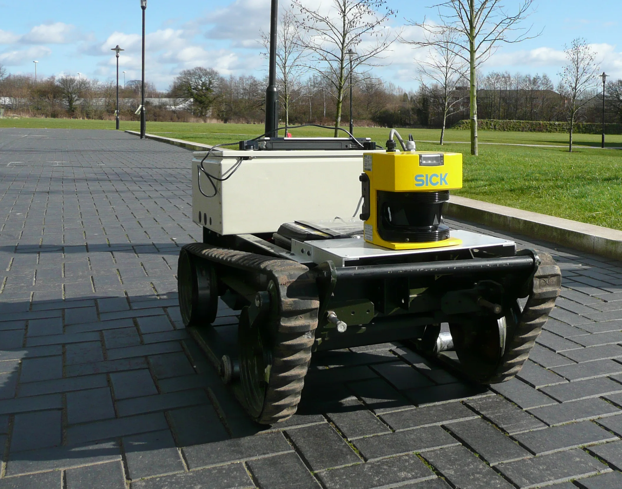
Ground robots can use mapping to support routes through unfamiliar environments. For a proposed warehouse deployment, include moved shelving and repeated aisles in the evaluation rather than testing only a distinctive, empty route.
Unmanned aircraft can use camera-based estimation as an external navigation input where satellite positioning is unavailable. ORB-SLAM3 supplies examples for the EuRoC drone dataset, while PX4 documents how external estimates enter an aircraft estimator. Those are separate capabilities: successful dataset playback does not establish an integrated aircraft's control performance. ORB-SLAM3 examples, PX4 integration guide
Autonomous underwater vehicles can use sonar observations to constrain accumulated navigation error. Zhang and colleagues matched features between side-scan sonar images and evaluated trajectory correction using data from a Hugin AUV. Their study identifies limited distinctive features and missing three-dimensional bathymetric information as difficulties. It demonstrates a particular acoustic mapping approach, not interchangeability between terrestrial lidar software and underwater sonar. Side-scan sonar SLAM study
Evaluate the whole navigation chain
Define the trial around the mission rather than an algorithm name. Request the exact sensors, software revision, calibration, map format, processor, and route conditions. Record trajectory error against an independent reference, pose latency, tracking interruptions, correction jumps, and recovery behavior. State how trajectories were aligned before comparing error values.
For example, the ORB-SLAM3 repository notes that TUM-VI ground truth is available in the room where sequences begin and end. Its error measurement therefore cannot establish accuracy at every point along the intervening route. A benchmark result needs its measurement boundary attached. ORB-SLAM3 evaluation documentation
A useful demonstration should include startup, sustained operation, a revisit, and an interruption, with the intended controller consuming the estimates. Define the response to invalid localization for that vehicle and operating area: continuing on stale coordinates must not be an accidental default. A ground robot's stop and an aircraft's recovery maneuver require different designs.
Choose SLAM when building and reusing a map solves the mission's positioning problem, and qualify the complete chain from observation to vehicle response.
Sources
- Cadena et al., Past, Present, and Future of SLAM: scholarly tutorial and survey explaining architecture, data association, and robustness limits.
- Campos et al., ORB-SLAM3 paper: primary research on visual-inertial estimation, scale, map reuse, and recovery.
- Mur-Artal and Tardos, ORB-SLAM2 paper: primary research explaining monocular scale, stereo/depth inputs, sparse maps, and tracking loss.
- Hess et al., Real-Time Loop Closure in 2D LIDAR SLAM: primary research abstract describing scan-to-submap constraints and loop closure.
- ORB-SLAM3 repository documentation: official configuration, calibration, dataset, and evaluation guidance.
- Cartographer algorithm walkthrough: official technical documentation of submaps, occupancy grids, optimization, and compute tradeoffs.
- LIO-SAM repository documentation: official input requirements and timing/alignment troubleshooting guidance.
- ROS REP 105, Coordinate Frames for Mobile Platforms: the official ROS convention for map, odometry, and robot frames.
- PX4 external-position estimation guide: official main-branch documentation of external pose interfaces and coordinate/timing requirements.
- Zhang et al., A Fully-automatic Side-scan Sonar SLAM Framework: primary underwater research, revised December 2023, evaluated with real AUV data.
- Tagliabue et al., LION: primary research describing observability assessment and supervision across odometry sources.
- NTNU LiDAR Degeneracy Datasets: the research team's record of tunnel and fog-corridor aerial-robot data collection.
- Nav2 Jazzy Costmap 2D documentation: official navigation documentation for map layers, footprint, and unknown-space configuration.
Last checked: September 7, 2026.